
Process for preparing a polyethylene product in a polymerization loop reactor

a technology of polyethylene product and polymerization loop, which is applied in the direction of chemical/physical/physical-chemical stationary reactors, chemical apparatus and processes, chemical/physical/physical-chemical processes, etc., can solve the problem of minor increase in the concentration of solid polymer withdrawn from the polymerization loop reactor, and achieves the effect of increasing the efficiency of the settling legs, reducing the concentration, and increasing the solid polymer concentration

Active Publication Date: 2016-03-29
TOTAL RES & TECH FELUY
View PDF13 Cites 0 Cited by
  • Summary
  • Abstract
  • Description
  • Claims
  • Application Information

AI Technical Summary

Benefits of technology

[0014]The inventors have surprisingly found that the above-provided process creates a stratification of the polyolefin slurry inside said at least one horizontal part of said interconnected pipes provided with one or more settling legs. This stratification has the advantage of increasing the solid polymer concentration in the bottom part of said at least one horizontal part of the pipe provided with one or more settling legs. Consequently and advantageously, the polyolefin slurry withdrawn from the loop reactor will contain an increased amount of solid polymer and a decreased amount of diluent and other reactants, such as monomer. This is advantageous because the process minimizes or obviates the need for elaborate downstream processing of the polyolefin slurry. As a further advantage, the cost of production will be decreased because less monomer and diluent will be fed to the separation and purification processes. The concentration in polymer solids in the stratified flow can be at most 10 wt % higher than the concentration in the main flow in other reactor sections with no stratification. The concentration in polymer solids in the densest part of the stratified flow can be between 45 wt % to 60 wt %, ideally between 55 wt % and 60 wt %.
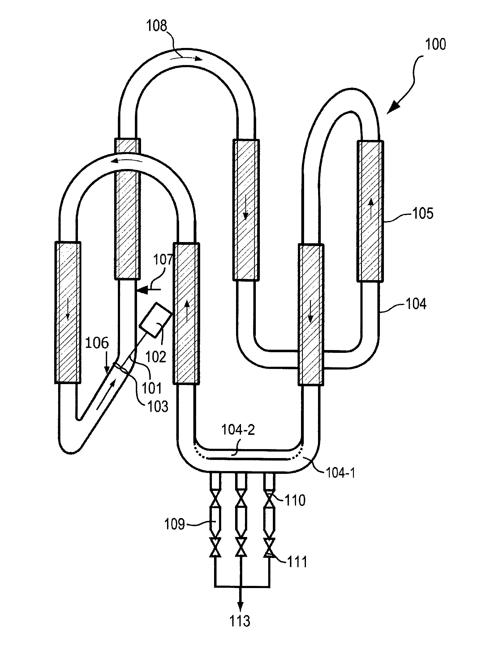
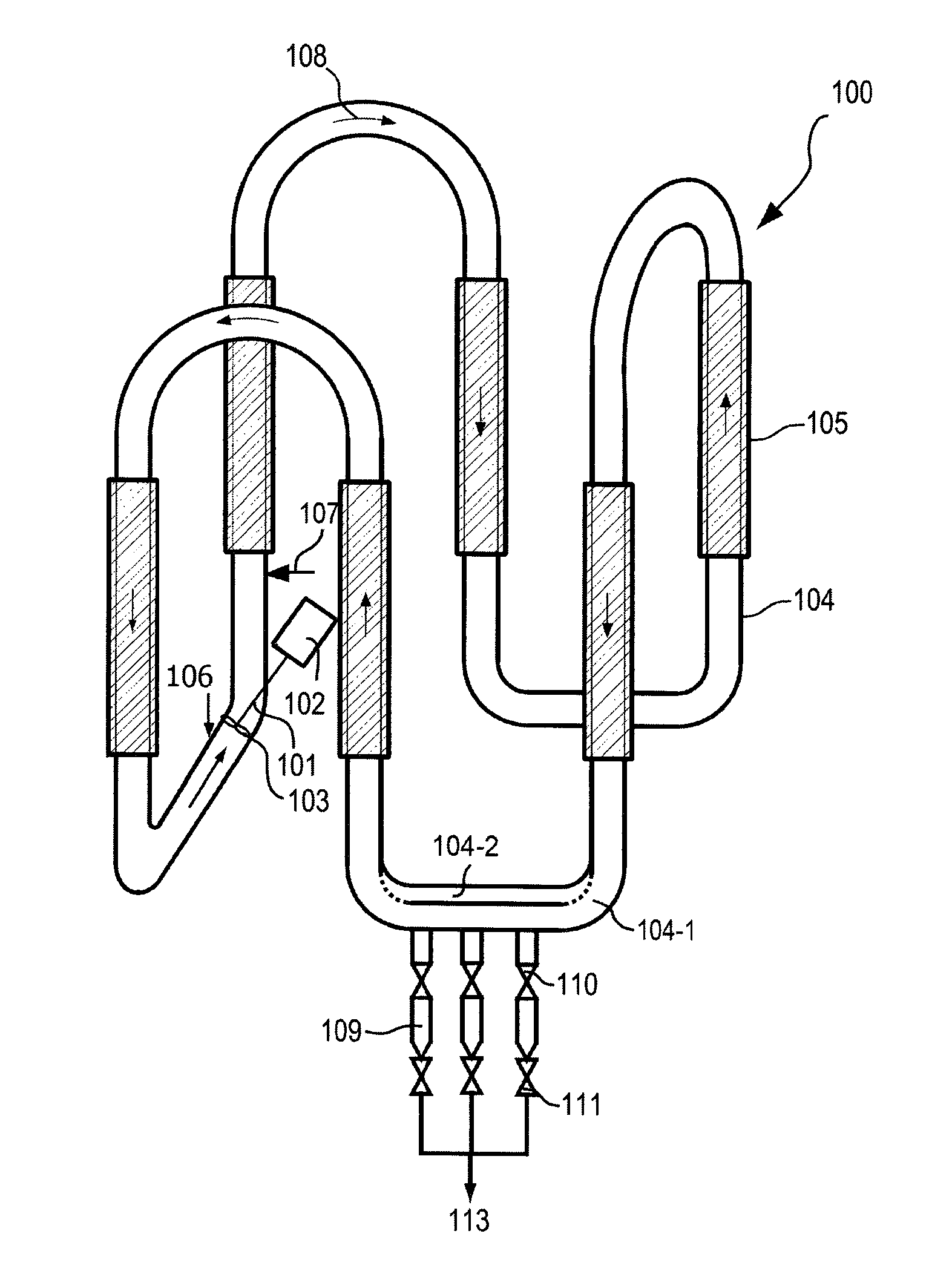
[0015]In a second aspect, the present invention relates to a loop reactor suitable for a polyolefin polymerization process comprising a plurality of interconnected pipes defining a flow path for a polyolefin slurry, means for introducing olefin monomer, polymerization catalyst and diluent into said reactor, one or more settling legs provided on at least one horizontal part of said interconnected pipes, and a pump suitable for maintaining said polyolefin slurry in circulation in said loop reactor, wherein the bottom ends of at least two vertical pipes are connected to each other by two horizontal pipes, and wherein at least one of said two horizontal pipes is provided with one or more settling legs. Preferably, the present invention provides a loop reactor suitable for a polyolefin polymerization process comprising: a plurality of interconnected pipes defining a flow path for a polyolefin slurry, means for introducing olefin monomer, polymerization catalyst and diluent into said reactor, one or more settling legs provided on at least one horizontal part of said interconnected pipes, and a pump suitable for maintaining said polyolefin slurry in circulation in said loop reactor; wherein the bottom ends of at least two vertical pipes are connected to each other by two horizontal pipes, and wherein at least one of said two horizontal pipes is provided with one or more settling legs, and wherein said two horizontal pipes are configured to reduce the circulation velocity of the polyolefin slurry inside at least one horizontal part of said interconnected pipes provided with one or more settling legs by at least 20% and at most 60% compared to the circulation velocity inside the remainder of said loop reactor.
[0016]The present invention provides advantages over the prior art. A loop reactor as described above, significantly increases the efficiency of the settling legs, resulting in a product slurry withdrawn from the loop reactor with a higher solid polymer concentration and a lower concentration of diluent and other reactants, such as monomer. Therefore, the loop reactor is advantageous for obtaining product slurry in an efficient and hence economical way.

Problems solved by technology

The use of settling legs, however, results only in a minor increase in the concentration of solid polymer withdrawn form the polymerization loop reactor.
The above-described known processes and apparatuses have the disadvantage that the product slurry withdrawn from the reactor still contains a large amount of diluent and other reactants, such as monomer, which implies the necessity to subsequently separate them from the solid polymer particles and to reprocess them for the purpose of reusing them in the reactor.

Method used


Image

  • Process for preparing a polyethylene product in a polymerization loop reactor
  • Process for preparing a polyethylene product in a polymerization loop reactor
  • Process for preparing a polyethylene product in a polymerization loop reactor

Examples


example 1

[0110]Polyethylene is prepared by feeding ethylene monomer, catalyst, hexene comonomer, hydrogen, and isobutane diluent to a single slurry loop reactor. The loop reactor comprises 4 vertical pipes, 2 upper horizontal segments and 2 lower horizontal segments of reactor piping, joined end to end by junctions such as elbows to form a complete loop. The developed length of the reactor is about 250 m. The vertical sections of the pipe segments are provided with heat jackets. The polymer slurry is circulated by an impeller driven by a motor. One of the horizontal segments is provided with 4 settling legs.

[0111]In this example, the desired effect is obtained by reducing the circulation velocity of the polyethylene slurry from 9 m / s in the remaining sections of the loop reactor to 5 m / s in the settling legs section. This velocity reduction is achieved by increasing the reactor inside diameter from 56.0 cm in the remaining sections of the reactor to 75.0 cm in the settling legs section. The ...

example 2

[0112]Polyethylene is prepared by feeding ethylene monomer, catalyst, hexene comonomer, hydrogen, and isobutane diluent to a single slurry loop reactor. The loop reactor comprises 4 vertical pipes, 2 upper horizontal segments and 3 lower horizontal segments of reactor piping, joined end to end by junctions such as elbows to form a complete loop. The bottom ends of two vertical pipes are connected to each other by two horizontal pipes, each provided with 3 settling legs. The vertical sections of the pipe segments are provided with heat jackets. The polymer slurry is circulated by an impeller driven by a motor.

[0113]The desired effect is obtained by reducing the circulation velocity of the polyethylene slurry from 9.5 m / s in all sections of the loop reactor to 5.5 m / s in the settling legs section, while keeping 9.5 m / s in the remaining sections of the reactor. This velocity reduction is achieved by splitting the flow in the settlings legs section into 2 horizontal sections, both equip...


PUM

PropertyMeasurementUnit
pressureaaaaaaaaaa
pressureaaaaaaaaaa
pressureaaaaaaaaaa

Abstract

A process for preparing polyolefin in a polymerization loop reactor can include feeding olefin monomer, liquid diluent, polymerization catalyst, optionally hydrogen, and optionally olefin co-monomer into the polymerization loop reactor. The process can include polymerizing the olefin monomer and optionally the olefin co-monomer to produce a polyolefin slurry in the polymerization loop reactor. The polymerization loop reactor can include a plurality of interconnected pipes defining a flow path for the polyolefin slurry. The polymerization loop reactor can include one or more settling legs provided on at least one horizontal part of the interconnected pipes. The circulation velocity of the polyolefin slurry inside at least one horizontal part of the interconnected pipes provided with one or more settling legs can be reduced by at least 20% and at most 60% compared to a circulation velocity inside a remainder of the polymerization loop reactor.

Description

CROSS REFERENCE TO RELATED APPLICATIONS[0001]This application is a national stage entry of PCT / EP2013 / 059217, filed on May 3, 2013, which claims priority from European Application No. 12166881.8, filed on May 4, 2012.FIELD OF THE INVENTION[0002]The present invention relates to a process for the preparation of a polyethylene product. In particular, the present invention relates to improvements in the removal of a polyethylene slurry from a polymerization loop reactor. The present invention relates as well to a loop reactor for polyethylene polymerization with improved product removal means.BACKGROUND OF THE INVENTION[0003]Polyolefins, such as polyethylene (PE), are synthesized by polymerizing monomers, such as ethylene (CH2═CH2). Because they are cheap, safe and stable to most environments and easy to be processed, polyolefins are useful in many applications. Polyethylene can be classified into several types, such as, but not limited to, LDPE (Low Density Polyethylene), LLDPE (Linear...

Claims


Application Information

Patent Timeline
Patent Type & Authority Patents(United States)
IPC IPC(8): C08F2/00C08F2/01B01J8/00B01J19/18C08F210/00B01J19/24C08F210/16
CPCC08F2/01B01J8/007B01J19/1837B01J19/1862B01J19/2455C08F210/16C08F10/02C08F2/14B01J2219/24C08F210/14C08F10/00C08F2/44
Inventor GIGUERE, ROBINMIGNON, DENISTANGUY, PHILIPPEFRADETTE, LOUIS
Owner TOTAL RES & TECH FELUY
Learn More