Variable geometry optical gas detector

a gas detector and variable geometry technology, applied in the field of variable geometry optical gas detectors, can solve the problems of cumbersomeness, inability to use in compact forms and dimensions, luminous radiation, and considerable attenuation, and achieve the effect of high resistance and reliability, easy and economical production

Active Publication Date: 2016-03-29
N E T SRL
View PDF42 Cites 7 Cited by
  • Summary
  • Abstract
  • Description
  • Claims
  • Application Information

AI Technical Summary

Benefits of technology

[0020]More specifically, the purpose of the present invention is to provide a variable geometry optical gas detector able to guarantee a high degree of accuracy as regards determining the quality and quantity of gas.
[0021]A further purpose of the invention is to provide a variable geometry optical gas detector which permits alternative optical paths to be realised configurable at the moment of construction and assembly of said detector depending on the nature of the gas to be identified.
[0022]A further purpose of the invention is to make available to users a variable geometry optical gas detector suitable for ensuring a high level of resistance and reliability over time, in addition such as to be easy and economical to produce.

Problems solved by technology

All these types of detectors have the drawback however of being cumbersome and not utilisable where compact forms and dimensions are required.
The typical drawback of this latter type of embodiment relates to the fact that the luminous radiation, not following a rectilinear path and on various levels, is considerably attenuated due to the refraction thereof on the delimiting and / or reflector surfaces of the optical path.
A further drawback of these detectors relates to the fact of not being adaptable to the various types of gas since each sensor has a fixed optical path with a specific length for a certain type of gas.

Method used


Image

  • Variable geometry optical gas detector
  • Variable geometry optical gas detector
  • Variable geometry optical gas detector

Examples


Embodiment Construction

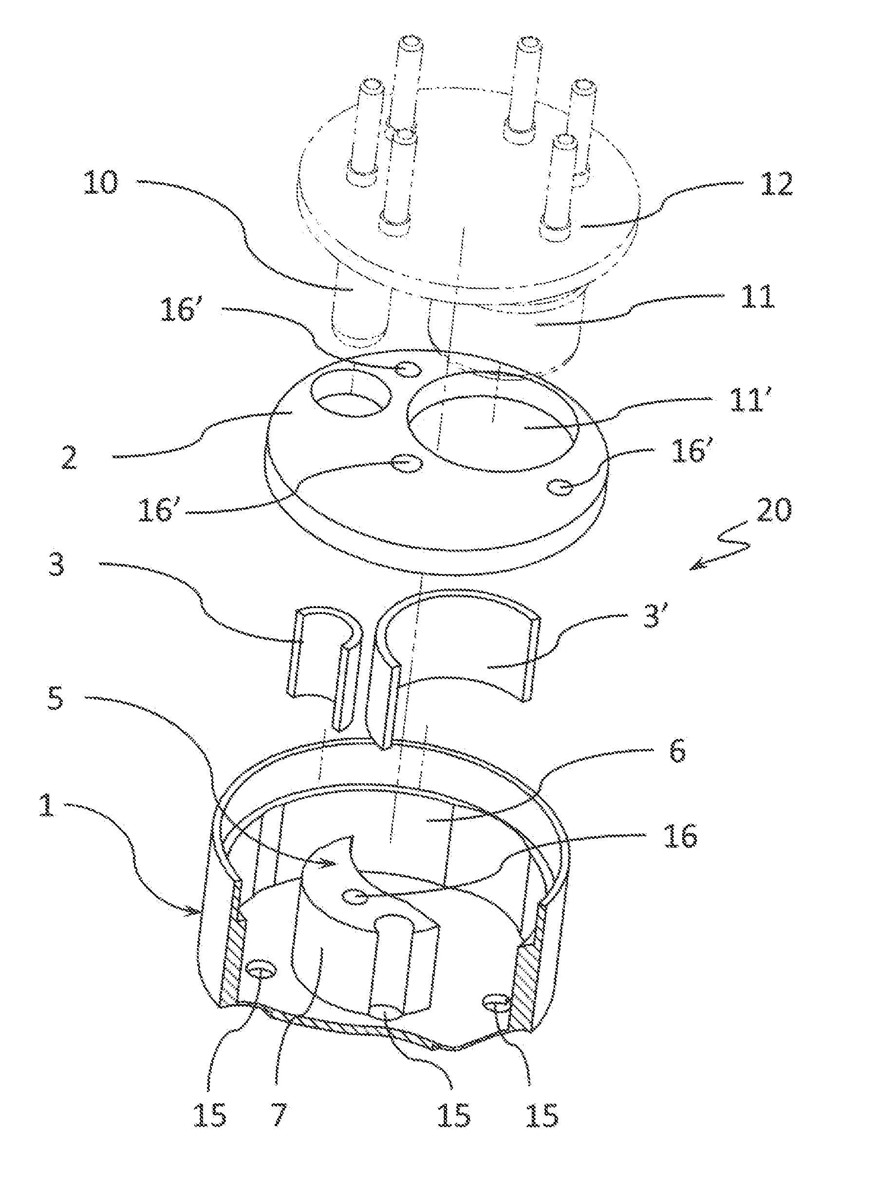
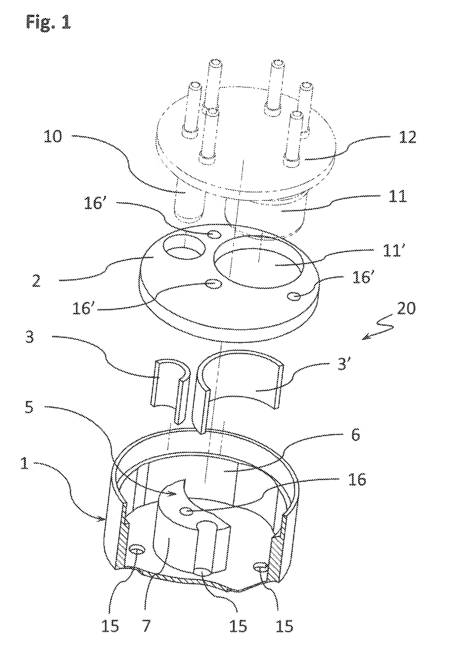
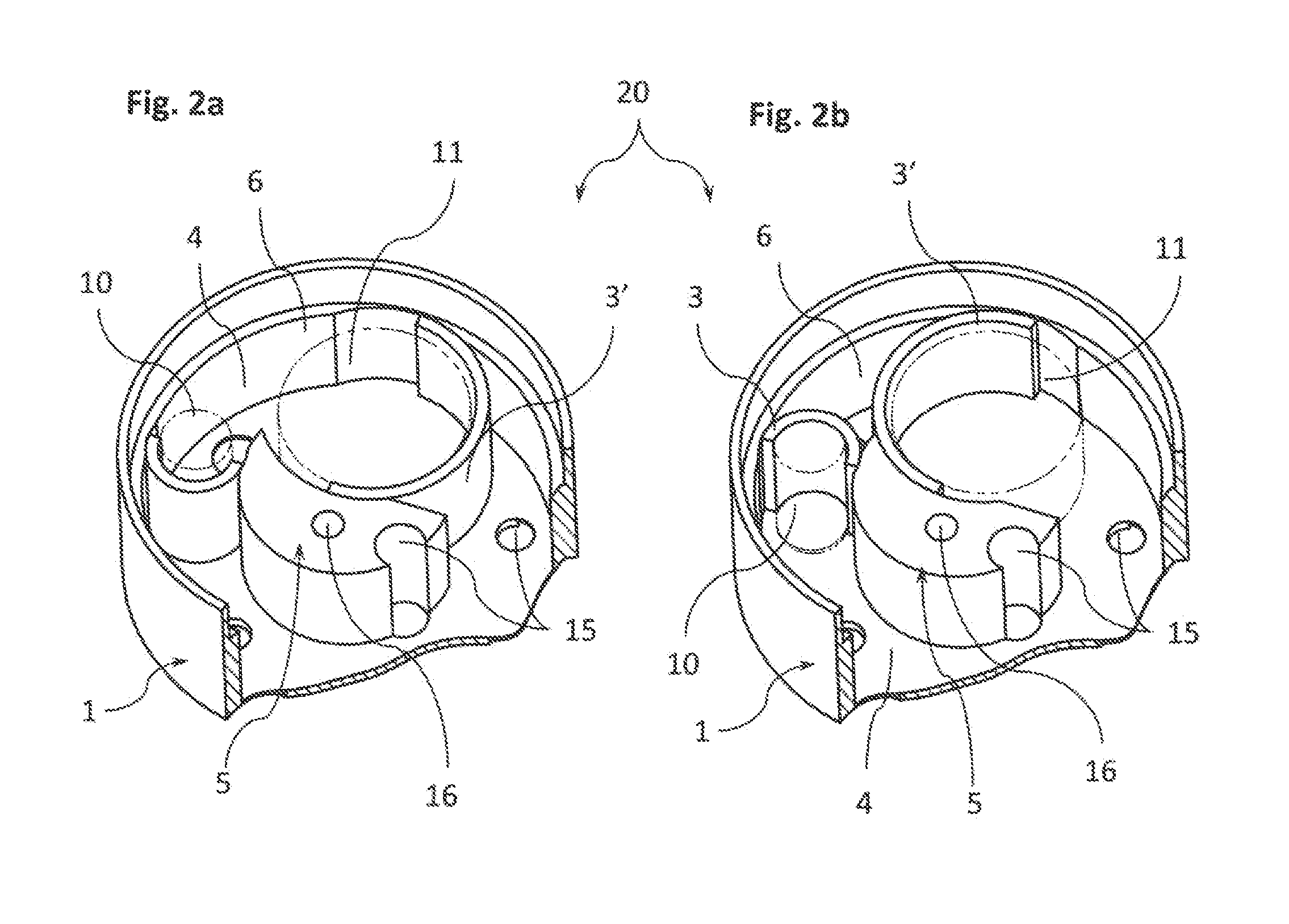
[0033]With initial reference to FIGS. 1, 2a and 2b, the variable geometry optical gas detector according to the present invention, globally denoted by reference numeral 20 and the optical part only of which is shown by way of example in FIGS. 2a and 2b, consists in its more general form of a cup-shaped body 1, surmounted by a disc-shaped lid 2. Said lid 2, shown in schematic form in FIG. 1, is provided with through apertures 10′ and 11′ in which an IR source 10 and an IR analyser 11 of the known type are inserted entirely or in part, borne by a circuit board; said circuit board 12, equally known, is attached with screws or equivalent means to the lid 2. Said IR analyser 11 and IR source 10 extend partially inside the body 1, after the lid 2 and the circuit board 12 have been coupled to said body 1.

[0034]According to the invention, the body 1 defines the seat for one or more reflectors 3 and 3′, shaped so as to optimally deviate and reflect the electromagnetic radiation emitted by th...


PUM

PropertyMeasurementUnit
sizeaaaaaaaaaa
lengthsaaaaaaaaaa
electromagneticaaaaaaaaaa

Abstract

An optical gas detector (20) in metal or other suitable material, comprising a cup-shaped body (1), with upper mouth (9) closed by a lid (2) the bottom of which (8) is flat and provided with a plurality of through holes (15) variously arranged, which place said detector (20) in communication with the outside environment, and inside which an IR source (10) and an IR analyser (11) are placed, borne by an overlying circuit board (12). The inner lateral surface of the body (1) forming a first reflector wall (6) having a regular or irregular annular extension and defining, in conjunction with a second convex or concave reflector wall (7, 7′) of a shaped appendage (5) and with one or more reflectors (3, 3′, 21, 22, 23,24,25) pre-inserted and positioned in the body (1), a multiplicity of geometrically alternative optical paths (4, 4′, 4″, 4′″) of the electromagnetic radiation emitted by the IR source (10) and detected by the IR analyser (11).

Description

CROSS-REFERENCE TO RELATED APPLICATION[0001]This application claims priority to Italian Application No. MI2013A000478, filed Mar. 29, 2013, the disclosure of which is incorporated by reference herein in its entirety and made a part of this application.BACKGROUND OF THE INVENTION[0002]1. Field of the Invention[0003]The present invention relates to a variable geometry optical gas detector. More specifically, the present invention relates to a gas detector of the non-dispersive optical type in which the electromagnetic radiation in the infrared band is emitted by a source for the purpose and channelled to an analyser through an optical path of variable geometry and configurable depending on the nature of the gas to be detected.[0004]2. Description of the Related Art[0005]In the prior art, detectors of gaseous substances are known of which function on the optical spectrophotometry principle by means of dispersive and non-dispersive sensors. These sensors detect the absorption of part of...

Claims


Application Information

Patent Timeline
Patent Type & Authority Patents(United States)
IPC IPC(8): G01N21/61G01N21/03G01N21/3504
CPCG01N21/61G01N21/0303G01N21/3504G01N2021/036G01N2021/0307G01N2021/0378
Inventor FRIGO, GIACOMINO
Owner N E T SRL
Why Eureka
Try Eureka