
Device and process for determining a runway state, aircraft including such a device and piloting assistance system using said runway state

a technology for determining the state of a runway and a piloting assistance system, which is applied in the direction of aircraft ground control, aircraft traffic control, instruments, etc., can solve the problems of difficult adhesion measurement, ineffectiveness, and difficult prediction of braking performance of aircraft on a runway said to be contaminated, so as to improve the reliability of estimation, simplify calculations, and accurate correlate determined runway states

Active Publication Date: 2016-03-29
AIRBUS OPERATIONS (SAS)
View PDF14 Cites 6 Cited by
  • Summary
  • Abstract
  • Description
  • Claims
  • Application Information

AI Technical Summary

Benefits of technology

This approach provides a more accurate and objective assessment of the runway state, enabling better decision-making for pilots and airport management by correlating adhesion measurements with the actual runway conditions, ensuring safer operations and efficient use of runways.

Problems solved by technology

Yet, a plane's braking performances on a runway said to be contaminated are very difficult to predict because of the difficulty in having a reliable and accurate knowledge of the runway's contribution to the plane's deceleration, in particular in terms of adhesion and projection drags and displacements in the case of thick contaminants.
Initial solutions to estimate the state of the runway have already been implemented, but today, the runway's adhesion measurements are very difficult, not very effective, not reliable and hard to transpose from the context of the measurement means used to that of a plane on the take off or landing roll on the same runway.
In particular, it is known that the measurement of the runway's adhesion thanks to friction engines or “mu-meters”, for example towed vehicles or special vehicles, that provide results that are ill-assorted, potentially inconsistent among themselves, not representative for an airplane because of the different scales of phenomena such as the loads and tire performance.
In addition, such measurements require closing the runway for several minutes, which may be harmful considering the ever increasing airport traffic.
However, this approach only provides an indication that is strongly based on the location where the inspection was carried out.
Furthermore, it requires closing the runway for long periods of time (around twenty minutes), which is not compatible with airport traffic.
However, this solution is subjective, depends on the plane and takes into account contributions other than wheel braking (as the pilot is not able to identify the exact part of the various means of braking of his plane: aerodynamic drag, engine thrust or counter-thrust and wheel braking).
These treatments performed, take into account the type of plane involved because the measurement of the deceleration alone does not allow for an easy utilization by another plane.
In addition, these treatments are long, manual and not compatible with an intensive use of an airport where an estimation of the runway state is required in a brief period before the next plane performs a take off or landing roll on the runway.
However, this information is simply not useable in a satisfactory timeframe to notify the approaching planes.
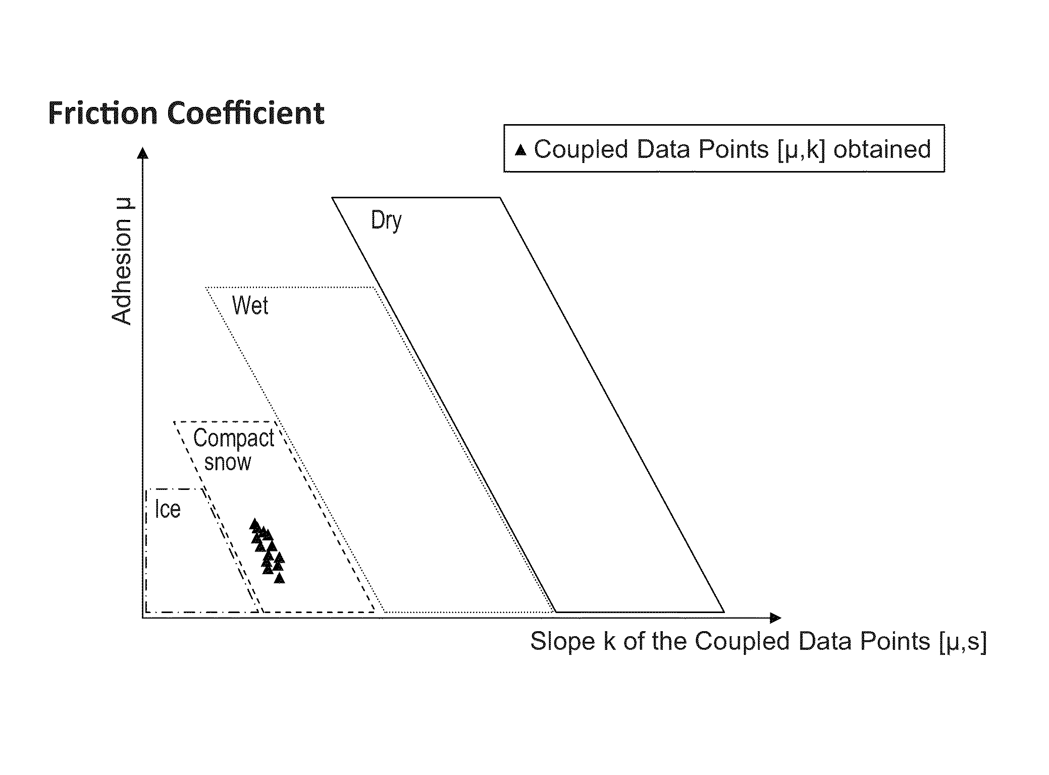
One difficulty in determining the state of the runway resides in the evaluation of an adhesion coefficient μ value concerning the physical environment of the plane, where this physical environment not only concerns the runway but also the plane itself (for example its tires).
From these examples, the sole estimation of an adhesion coefficient μ does not make it possible to correlate, in a reliable and precise manner, the measurements with a runway state.

Method used


Image

  • Device and process for determining a runway state, aircraft including such a device and piloting assistance system using said runway state
  • Device and process for determining a runway state, aircraft including such a device and piloting assistance system using said runway state
  • Device and process for determining a runway state, aircraft including such a device and piloting assistance system using said runway state

Examples


Embodiment Construction

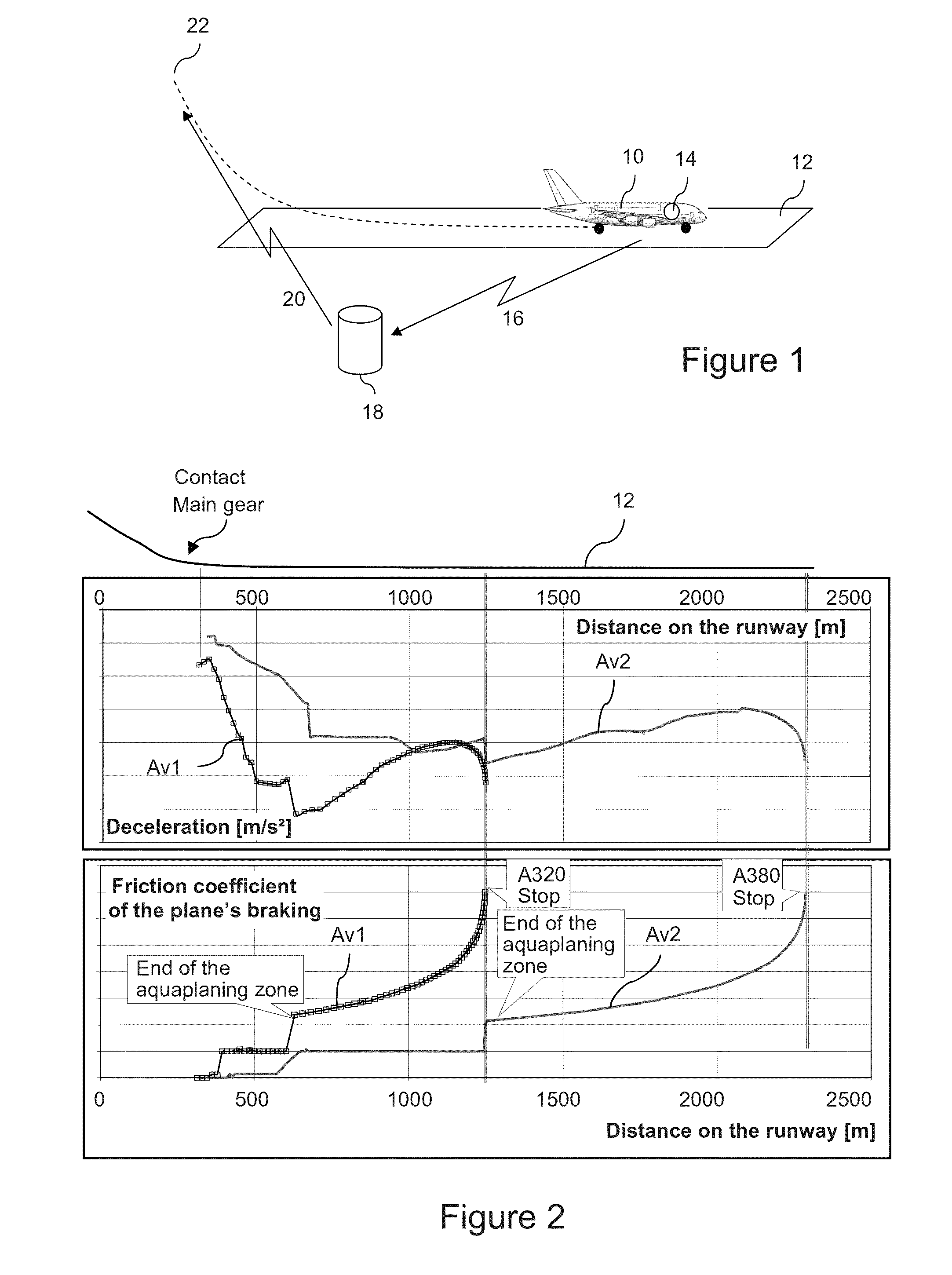
[0058]In FIG. 1, a plane 10 at the end of the landing roll / braking phase on an airport runway 12 is represented. Said plane 10 is equipped with a device 14, object of the invention, able to determine the state of the runway 12.

[0059]Through a communication link 16 provided for this purpose, the plane 10 that determines the state of the runway on-board, communicates said state to a central station on the ground 18 at the airport. As a variant, the measurement performed on the plane 10 can be forwarded to the ground station 18, who in turn determines the state of the runway as set forth in the invention. This ground station, after potential internal processing, communicates (20) a runway state to the planes 22 in the approach phase for landing or those ready for take-off.

[0060]The latter in turn will officiate as the plane 10 at the end of their landing or take-off to enhance the central station 18 with additional information about the state of the runway, in order to achieve in parti...


PUM


Abstract

This invention relates to a device and process for determining an airport runway state (12), as well as for using such data. The process includes: acquisition (A1) of measurement data pertaining to at least one physical size of an aircraft (10), during the take off or landing roll phase of the aircraft on said runway; obtaining (A2), using the data acquired, a plurality of estimated adhesion values “μ” of the runway, corresponding to a respective plurality of taxiing moments of the aircraft; obtaining (A3), using the data acquired, a slip ratio value “s” of at least one of the aircraft's wheels for each said taxiing moment, so as to obtain (A4) a plurality of coupled data points [s,μ]; and determination of a runway state by comparing (A5.2) the coupled data points [s,μ] profile with at least one predetermined profile.

Description

[0001]This application claims priority to French Patent Application No. 11 57041 filed Aug. 1, 2011, the entire contents of which are hereby incorporated by reference.BACKGROUND OF THE INVENTION[0002]1. Field of the Invention[0003]This invention relates to a device and process for determining the state of a runway, as well as to an aircraft's takeoff and / or landing assistance system and process, and to aircraft equipped with such devices and systems.[0004]2. Discussion of Prior Art[0005]During landing and takeoff phases, and more generally when a plane is on the take off or landing roll, being aware of the state of the runway surface is of the utmost importance. Indeed, predicting the plane's braking performance depends on said awareness. Thus it is possible: —To best estimate the distance needed to stop the plane in a concern for safety, —To not overestimate this stopping distance needed to bring the plane to a standstill and therefore to not overly penalize the runway and plane's ...

Claims


Application Information

Patent Timeline
Patent Type & Authority Patents(United States)
IPC IPC(8): G08G5/06B60T8/1763G08G5/00B64C25/42B60T8/17B60T8/172
CPCB60T8/172B60T8/1703B64C25/42G08G5/06G08G5/0013G08G5/0021G08G5/0086G08G5/065B60T2210/12B60T2210/13
Inventor JONES, LOGAN
Owner AIRBUS OPERATIONS (SAS)
Learn More