Vaginal dilator for use in gynecologic examination

a vaginal dilator and gynecologic technology, applied in the field of gynecologic examination instruments, can solve the problems of inconvenient light source control, poor compact structure of the vaginal dilator, and inconvenient operation for medical staff, so as to achieve convenient operation and simple fabrication

Active Publication Date: 2016-04-05
SUN CHANGCHUN +1
View PDF12 Cites 2 Cited by
  • Summary
  • Abstract
  • Description
  • Claims
  • Application Information

AI Technical Summary

Benefits of technology

[0011]The switch may be an extended elastic conductive wire connected to one terminal of the light emitting element, and may be arranged above a pole of the power source. The upper dilating leaf may be pressed down to contact and mate with the upper press rod or the upper dilating leaf may be disengaged from the upper press rod to coordinately control connection or disconnection between the extended elastic conductive wire and the power source. The other terminal of the light emitting element is connected to the other pole of the power source. The extended elastic conductive wire connected to one terminal of the light emitting element is used as the switch, and may coordinately mate with the upper dilating leaf, which is simple in fabrication and convenient in operation.
[0016]The light emitting element may be an LED lamp, which is compact and does not occupy a main portion of the upper press rod, thereby preventing the view passage from blockage during examination.

Problems solved by technology

However, in this design, the structure of the vaginal dilator is not compact and is not simple in operation.
However, upon the opening of the lamp, the lamp is steadily on until the battery is exhausted.
Consequently, it is not convenient for a medical staff to control the light source and it is also unfavorable to saving of energy and reuse of the power source.

Method used


Image

  • Vaginal dilator for use in gynecologic examination
  • Vaginal dilator for use in gynecologic examination
  • Vaginal dilator for use in gynecologic examination

Examples


Embodiment Construction

[0026]Reference will now be made in detail to the embodiments, examples of which are illustrated in the accompanying drawings, wherein like reference numerals refer to the like elements throughout. The embodiments are described below to explain the present invention by referring to the figures. The drawings are for illustration purpose only, and shall not be construed as limitations to the present invention. For better illustration of the following embodiments, some parts or components would be omitted, scaled up or scaled down in the drawings, which are not indicative of the practical sizes. For a person skilled in the art, it shall be understandable that some commonly known structures and description thereof are omitted for brevity.

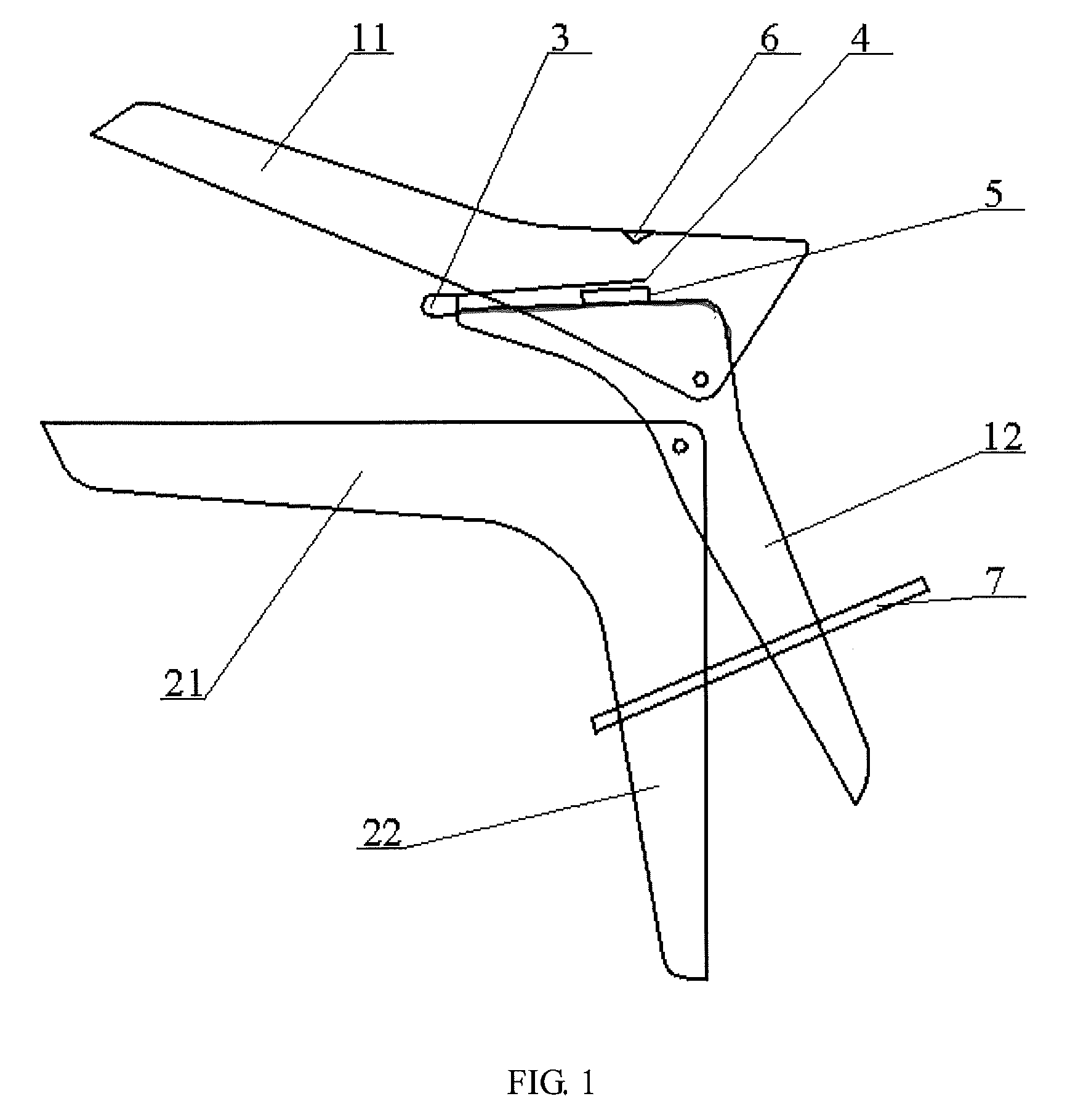
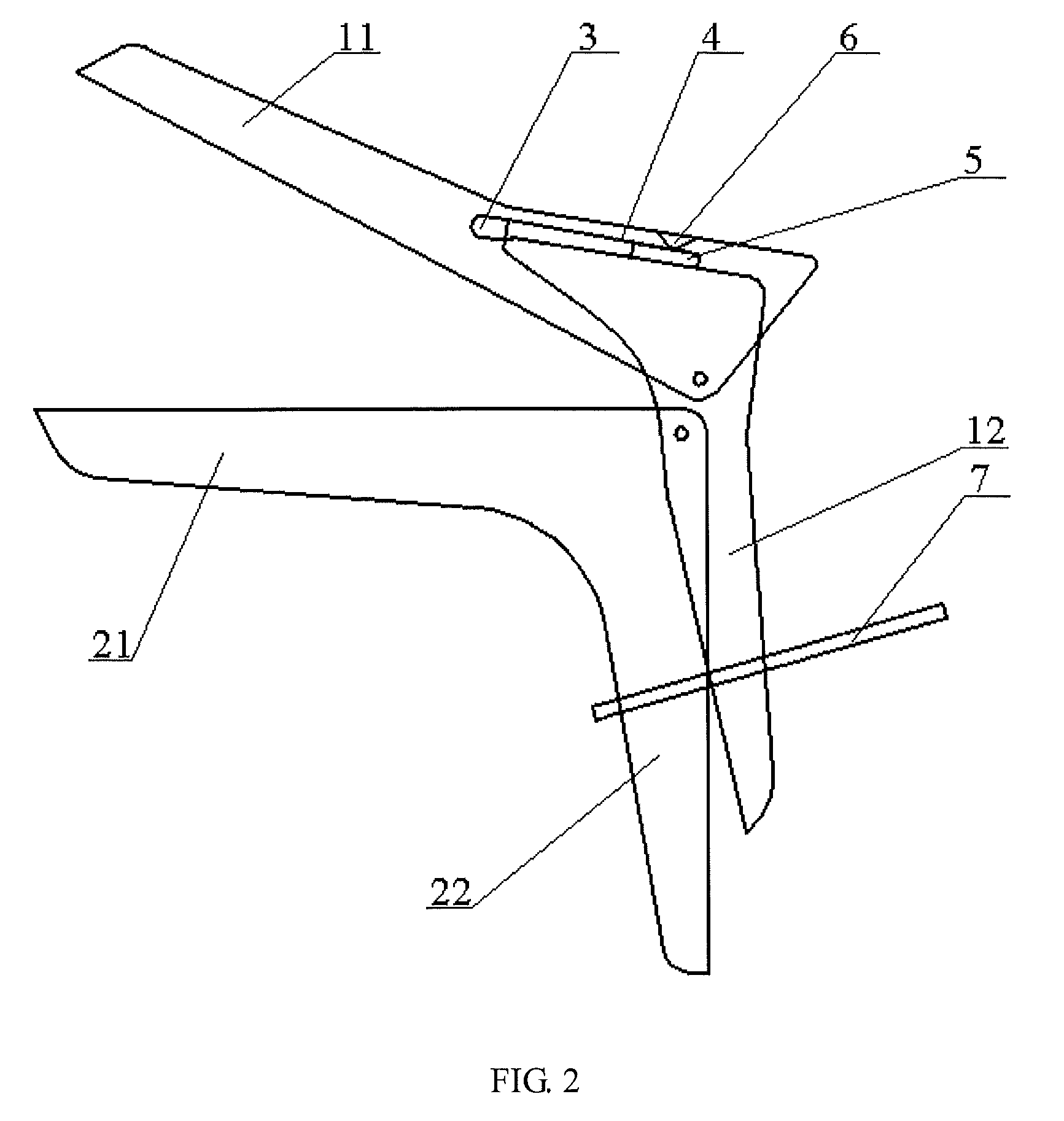
[0027]Referring to FIG. 1 to FIG. 5, a vaginal dilator according to one or more embodiments comprises an upper dilating member 1 and a lower dilating member 2 that are hinged to each other, wherein the upper dilating member 1 comprises an upper dilating...


PUM


Abstract

A vaginal dilator for use in gynecologic examination. The vaginal dilator comprises an upper dilating member and a lower dilating member that are hinged to each other, the upper dilating member comprising an upper dilating leaf and an upper press rod arranged at a tail portion of the upper dilating leaf, the lower dilating member comprising a lower dilating leaf and a lower press rod arranged at a tail portion of the lower dilating leaf. The upper dilating leaf is hinged to the upper press rod, and the upper rod is hinged to the lower dilating member, and the upper press rod is provided with a light emitting element, a switch and a power source, the switch being connected with the light emitting element. The upper dilating leaf is pressed down to contact and mate with the upper press rod or the upper dilating leaf is disengaged from the upper press rod to coordinately control the switch to be connected to or disconnected from the power source.

Description

CROSS-REFERENCE TO RELATED APPLICATIONS[0001]This application claims priority benefit from Chinese utility model application No. 201420166878.8 filed on Apr. 4, 2014 in the State Intellectual Property Office of the People's Republic of China issued on Sep. 3, 2014 as ZL 201420166878.8, the disclosure of which is incorporated herein by reference in its entirety.BACKGROUND OF THE INVENTION[0002]1. Field of the Invention[0003]One or more embodiments relate to an instrument for use in gynecologic examination, and in particular, to a vaginal dilator for use in gynecologic examination.[0004]2. Description of the Related Art[0005]A vaginal dilator is an instrument commonly used for routine gynecologic examination. A doctor also needs assistance by a light source during examining a patient's vagina. At present, a conventional vaginal dilator has been provided with a light source. Typically, some vaginal dilators have a fixed lamp, wherein the lamp is connected to a battery box via an electr...

Claims


Application Information

Patent Timeline
Patent Type & Authority Patents(United States)
IPC IPC(8): A61B1/32A61B17/02A61B1/06
CPCA61B1/06A61B17/0206A61B17/0218A61B1/00036A61B1/0684A61B1/303A61B1/32A61B1/00042A61B1/0655
Inventor SUN, CHANGCHUNZHANG, MINGLEIGE, LEI
Owner SUN CHANGCHUN
Why Eureka
Try Eureka