Multi-purpose hitch tool

a multi-purpose, hitch technology, applied in the direction of manufacturing tools, vehicle cleaning, wheel mounting apparatus, etc., can solve the problems of difficult removal of rusted hitch pins, difficult to insert hitch mounts into hitch receivers, etc., to achieve efficient cleaning, improve the removal of components, and reduce rigidity

Active Publication Date: 2016-04-05
GODDARD JOSEPH
View PDF24 Cites 9 Cited by
  • Summary
  • Abstract
  • Description
  • Claims
  • Application Information

AI Technical Summary

Benefits of technology

[0006]According to another aspect of the invention, a multi-purpose hitch tool includes a removal device that is coupled with a first end of an elongated handle. The removal device is configured to remove a cotter pin from a hitch pin or to strike the hitch pin out of engagement with a hitch receiver. A brush assembly is coupled with a second end of the elongated handle and is configured to remove debris from an interior cavity of the hitch receiver. The brush assembly includes a first bristle array that is configured to scrape the debris from the interior cavity. A second bristle array is disposed over an opposite lateral side of the elongated handle from the first bristle array. The second bristle array is less rigid than the first bristle array and is configured to bend against an interior surface within the interior cavity to bias the first bristle array against an opposite interior surface. Accordingly, the multi-purpose hitch tool provides efficient cleaning of the hitch receiver, improved removal of components of the hitch assembly, and a design for organized storage within a vehicle.

Problems solved by technology

Commonly, rust and other debris may accumulate within the hitch receiver, making it difficult to insert a hitch mount into the hitch receiver.
However, rigid cotter pins and rusted hitch pins can be difficult for an operator to remove.

Method used


Image

  • Multi-purpose hitch tool
  • Multi-purpose hitch tool
  • Multi-purpose hitch tool

Examples


Embodiment Construction

[0027]For purposes of description herein, the terms “upper,”“lower,”“right,”“left,”“rear,”“front,”“vertical,”“horizontal,” and derivatives thereof shall relate to the invention as oriented in FIG. 1. However, it is to be understood that the invention may assume various alternative orientations, except where expressly specified to the contrary. It is also to be understood that the specific devices and processes illustrated in the attached drawings, and described in the following specification are simply exemplary embodiments of the inventive concepts defined in the appended claims. Hence, specific dimensions and other physical characteristics relating to the embodiments disclosed herein are not to be considered as limiting, unless the claims expressly state otherwise.

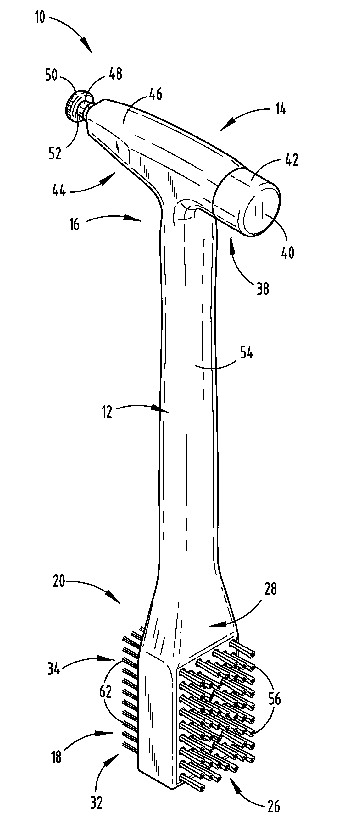
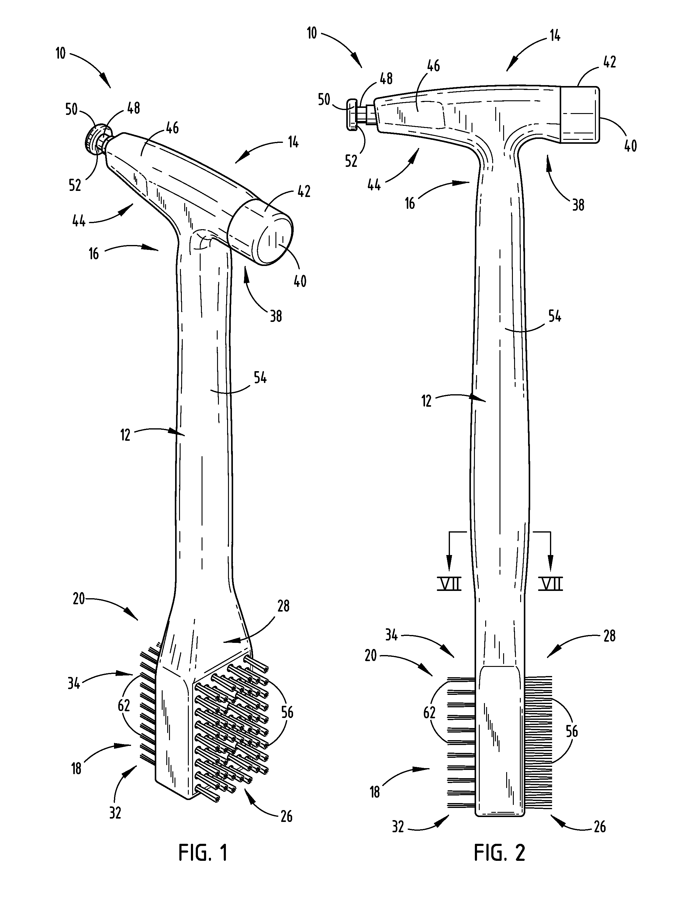
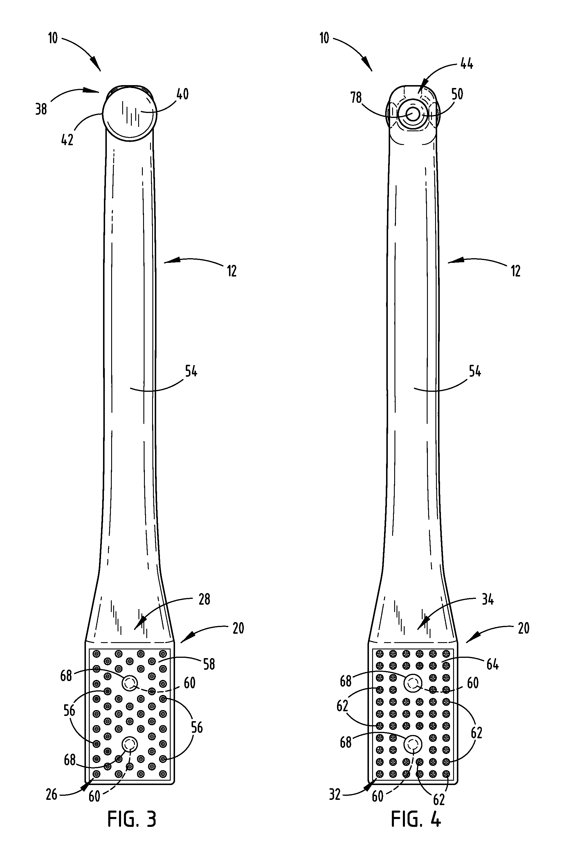
[0028]Referring to FIGS. 1-14D, reference numeral 10 generally designates a multi-purpose hitch tool that includes an elongated handle 12 and a removal device 14 coupled with a first end 16 of the elongated handle 12. A ...


PUM


Abstract

A multi-purpose hitch tool includes a removal device that is coupled with a first end of an elongated handle. The removal device is configured to remove a cotter pin from a hitch pin or to strike the hitch pin out of engagement with a hitch receiver. A brush assembly is coupled with a second end of the elongated handle and is configured to remove debris from an interior cavity of the hitch receiver. The brush assembly includes a first bristle array that is configured to scrape the debris from the interior cavity. A second bristle array is disposed over an opposite lateral side of the elongated handle from the first bristle array. The second bristle array is less rigid than the first bristle array and is configured to bend against an interior surface within the interior cavity to bias the first bristle array against an opposite interior surface.

Description

FIELD OF THE INVENTION[0001]The present invention generally relates to a multi-purpose hitch tool for cleaning and removing components of a hitch assembly, and more particularly to a multi-purpose hitch tool having a removal device and a brush assembly.BACKGROUND OF THE INVENTION[0002]It is generally understood that vehicles may be equipped with a hitch receiver for towing trailers or attaching other accessories. Commonly, rust and other debris may accumulate within the hitch receiver, making it difficult to insert a hitch mount into the hitch receiver. Once inserted, the hitch mount is typically attached to the hitch receiver with a hitch pin that extends through both the hitch mount and the hitch receiver. A cotter pin may be used to secure the hitch pin within the hitch receiver by passing though one end of the hitch pin. The removal of the cotter pin from the hitch pin is frequently done by inserting an operator's finger into a loop of the cotter pin and forcibly pulling the cot...

Claims


Application Information

Patent Timeline
Patent Type & Authority Patents(United States)
IPC IPC(8): B25F1/00B60D1/58B60S3/04B60B29/00
CPCB25F1/006B60D1/58B60S3/045B25F1/00B60B29/003
Inventor GODDARD, JOSEPH
Owner GODDARD JOSEPH
Why Eureka
Try Eureka