Vehicle seat

a technology for vehicles and seats, applied in the field of vehicles, to achieve the effect of effective massage, sufficient rigidity, and dissipation of for

Active Publication Date: 2016-04-05
FAURECIA AUTOSITZE
View PDF11 Cites 7 Cited by
  • Summary
  • Abstract
  • Description
  • Claims
  • Application Information

AI Technical Summary

Benefits of technology

[0006]Preferably, the support element is a fabric, in particular a carpet or a nonwoven or a synthetic component. It is of sufficient rigidity and expands when force acts upon it such that it can take up the force exerted by the fluid-fillable, hollow element, which is preferably a flexible or non-flexible fluid-tight bubble, and can dissipate said force into the surrounding cushion element, in particular into the surrounding foam.
[0007]According to one advantageous embodiment, a pressure element is located between the cover and the hollow element. This increases the force exerted for massaging purposes by the fluid-fillable, hollow element onto the vehicle passenger, such that a significantly more effective massage becomes possible. For this purpose, the pressure element can be molded onto the hollow element and / or connected to it. In addition, the pressure element can taper off toward the cover in order to transfer the force in a more selective or focused manner. The pressure element can also be attached to the cover and taper off in particular toward the hollow element. Furthermore, the pressure element can exhibit in particular a flat element that can be designed according to the desired massaging effect. Such a flat element can be made, for example, of leather or plastic. This increases the effective massage area.
[0008]According to one advantageous embodiment, the hollow element can be enclosed by a protective casing. It is made, for example, of plastic and during operation prevents that parts of the cushion element that surround the fluid-fillable, hollow element to enter into areas of the hollow element and thus interrupt the massaging function. This protective casing can be connected to the support element.

Problems solved by technology

The disadvantage of the known design is that the bubbles must be guided through the entire cushioning in order to introduce the force that acts upon them into the seat structure.

Method used


Image

  • Vehicle seat
  • Vehicle seat
  • Vehicle seat

Examples


Embodiment Construction

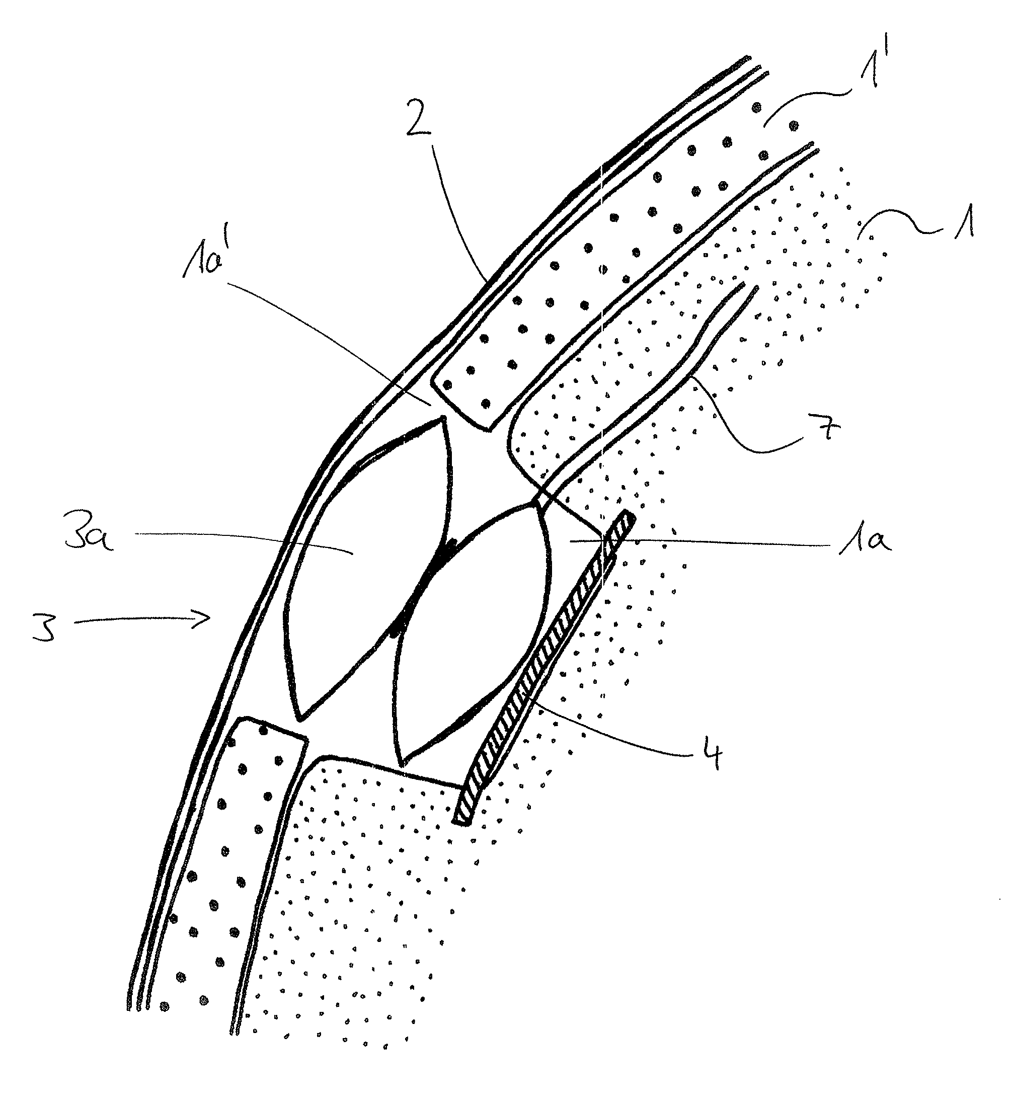
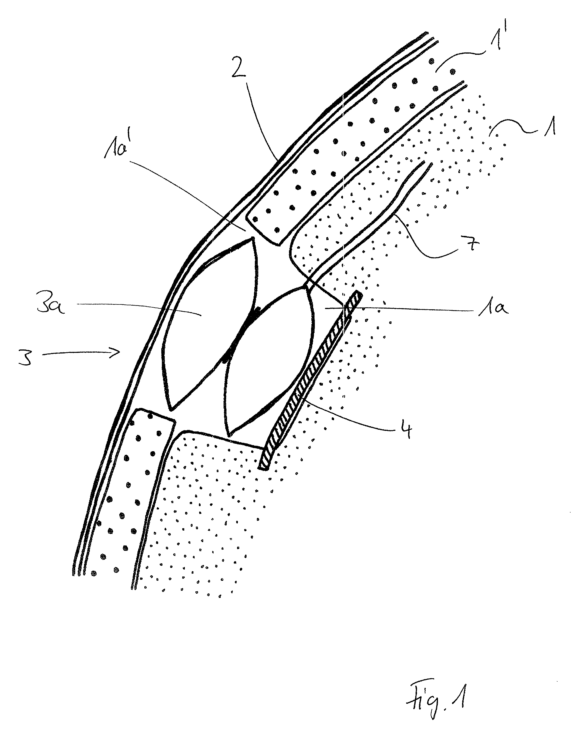
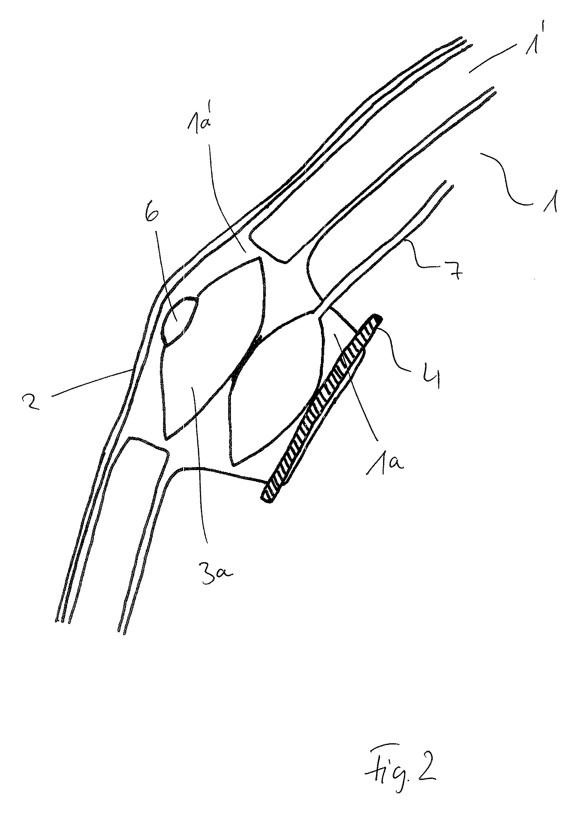
[0018]Essentially, all figures show a similar section of a part of the vehicle seat (e.g., seat section or back rest) that is facing the vehicle occupant. The reference characters are accordingly identical and essentially designate similar components.

[0019]In FIG. 1, the character 1 designates a first cushion layer or foam layer and 1′ designates an additional cushion layer or foam layer (hereinafter “layer” for short). The term “foam” will be used hereinafter. However, the foam layer can be any other suitable cushion element that does not include foam. Below, the term “foam layer” is not meant to be restrictive and can be understood as a cushion layer of any construction. Provided is a cover 2 that covers the layer 1 which is located at the side facing the vehicle occupant. Layers 1 and 1′ exhibit a recess 1a′ or an indentation 1a into which a fluid-fillable, hollow element 3a (hereinafter “bubble” for short) can be inserted, and which is part of a massage equipment 3. A support el...


PUM


Abstract

A vehicle seat having at least one cushion element including a foam layer (1, 1′), a cover (2) and a massage device (3), wherein the massage device (3) includes one or more fluid fillable, hollow elements (3a) that are located in open recesses (1a, 1a′) of the cushion elements (1, 1′) facing the cover (2) and are designed such that when filled with fluid, the mechanical expansion of the hollow elements (3) that effect the massaging force on the vehicle seat occupant expands toward the cover (2) and is supported by a support element (4) in a direction that faces away from the cover (2), and wherein the support element (4) is arranged such that it introduces the mechanical force resulting from the expansion of the hollow element (3a) and pointing away from the cover (2) into the at least one (1) and / or both the cushion elements (1, 1′).

Description

TECHNICAL FIELD[0001]The invention relates to a vehicle seat and more particularly, to a vehicle seat having a support element on which the hollow element that is to be filled with fluid can be supported, is provided in the cushion element, which is preferably designed as a layer, e.g., as a foam layer.BACKGROUND INFORMATION[0002]A seat of the generic kind is known, for example, from US 2011068611. It contains a seat cushion that includes a passage opening that houses hollow elements, which can be filled with fluid and are designed as pneumatic bubbles or chambers and part of a massage system. On the side of the bubble that faces away from the seat cover, they are supported by the seat structure in order to build up a respective counter-pressure when the bubbles are filled. The fill fluid is essentially considered to be air but a gel or a liquid is possible as well.[0003]The disadvantage of the known design is that the bubbles must be guided through the entire cushioning in order to...

Claims


Application Information

Patent Timeline
Patent Type & Authority Patents(United States)
IPC IPC(8): A61M11/00B60N2/44A61H9/00B60N2/90
CPCB60N2/448A61H9/00A61H2201/0134B60N2/976
Inventor WORLITZ, CLAUDIANEYRINCK, CHRISTIANHARMAN, RICHARDGAZANIOL, BENIOT
Owner FAURECIA AUTOSITZE
Why Eureka
Try Eureka