
Transmission unit

a technology of transmission unit and transmission shaft, which is applied in the direction of toothed gearings, mechanical equipment, belts/chains/gearrings, etc., can solve the problems of reducing the efficiency of a derailleur gearshift mechanism, and many gears that are redundant on the derailleur gearshift mechanism, etc., to achieve low cost, reduce the influence of driving force, and reduce the effect of environmental influences

Active Publication Date: 2016-04-05
PINION
View PDF31 Cites 3 Cited by
  • Summary
  • Abstract
  • Description
  • Claims
  • Application Information

AI Technical Summary

Benefits of technology

The present invention aims to provide a transmission unit for a muscle-powered vehicle that minimizes the impact of the drive, is light and compact, and can be manufactured cost-effectively.

Problems solved by technology

However, due to the nature of the design and depending on the layout, many of the gears are redundant on derailleur gearshift mechanisms.
The components of a derailleur gearshift mechanism are mounted externally on the frame of the bicycle and are hence directly exposed to environmental influences, such as water and dirt.
As a result, the high efficiency of a derailleur gearshift mechanism is reduced particularly quickly, which means that a large proportion of the expended muscular energy is lost through friction.
Due to the outward-lying design, the components are susceptible to damage caused by falls or contact with stones or branches.
As the chain runs at an—in some cases large—angle, and due to the frequent derailing of the chain between sprockets, the chain and the sprockets are especially subject to high wear and require regular replacement.
The known gearshift mechanisms for bicycles thus have the disadvantage that, in order to ensure perfect operation and a high level of efficiency, the level of maintenance required for a derailleur gearshift mechanism is correspondingly high and cost-intensive.
Consequently, internal-gear hubs are more low-maintenance than derailleur gearshift mechanisms, but they offer lower overall transmission ratios.
However, due to the arrangement of the internal-gear hub on the hub of the rear axle, on the one hand the weight of the rotating mass is increased, while on the other hand in the case of bicycles with rear suspension the unsprung mass seen in relation to the overall weight is also increased.
These factors have a disadvantageous effect on the riding characteristics of bicycles, particularly in the case of mountain bikes with rear suspension.
However, the disadvantages of this type of gearing mechanism include their large space requirements and high weight.

Method used


Image

  • Transmission unit
  • Transmission unit
  • Transmission unit

Examples


Embodiment Construction

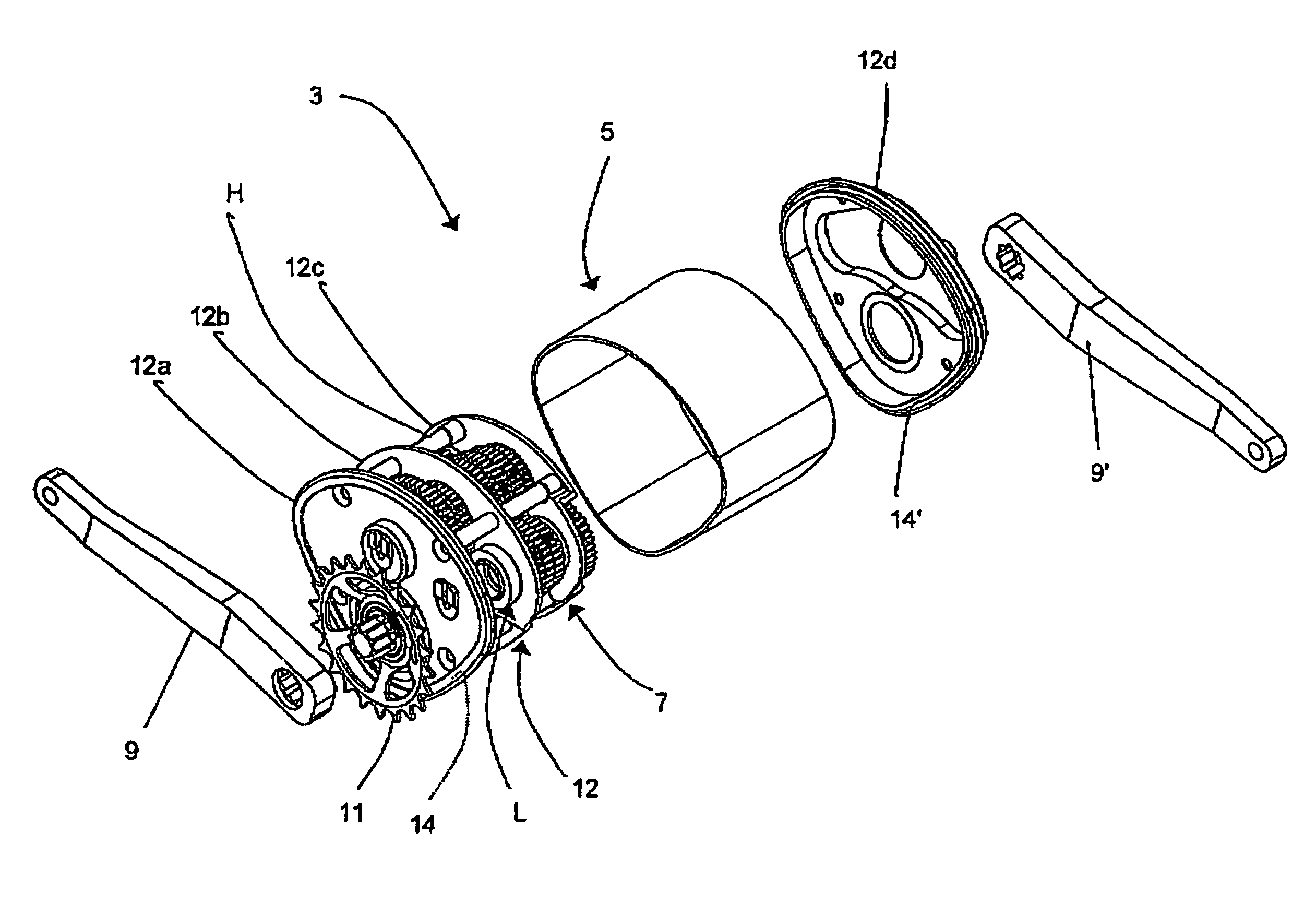
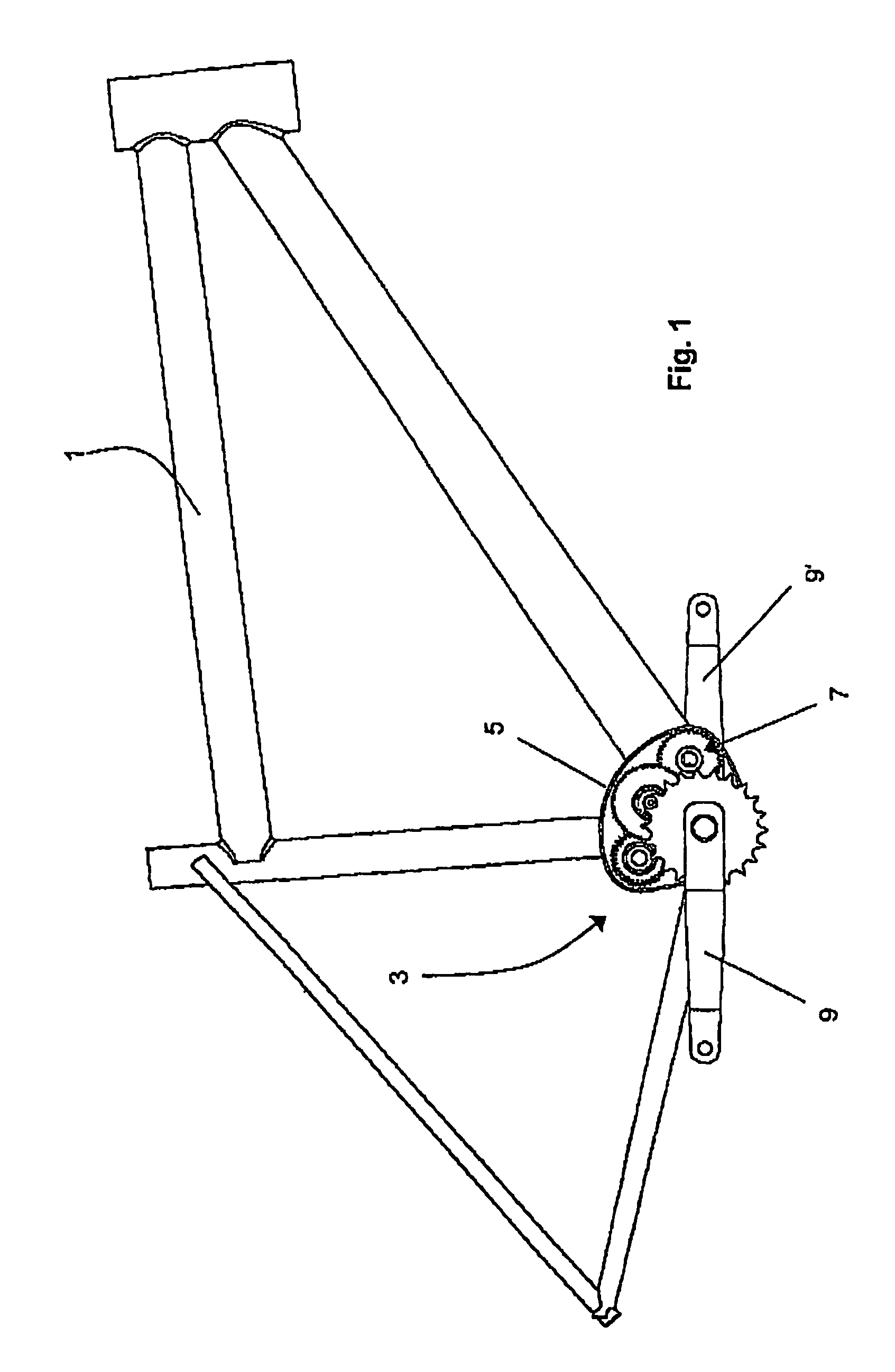
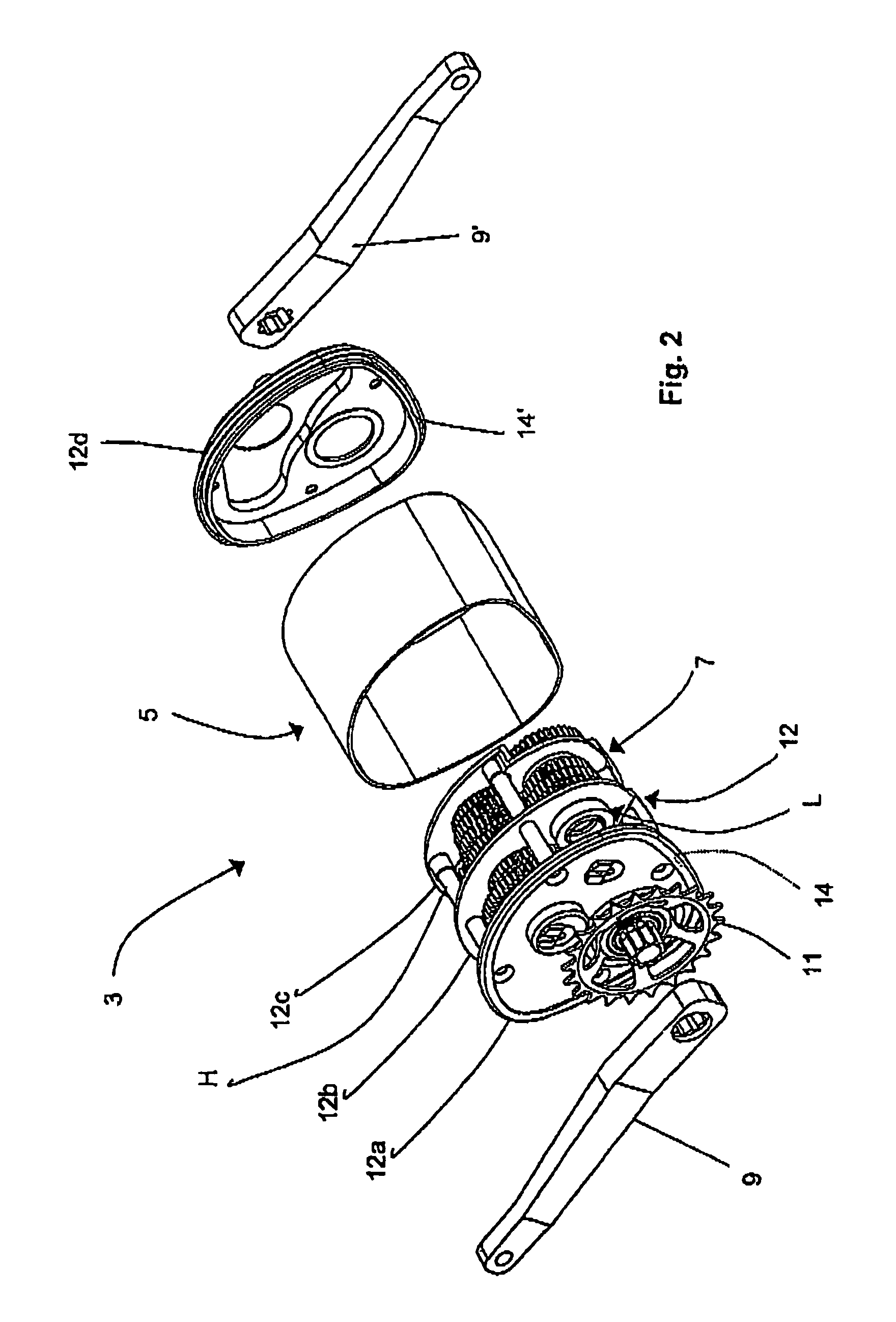
[0026]FIG. 1 shows a side view of a bicycle frame 1 with a multi-speed transmission 3, which has a gear housing 5 in which a transmission unit 7 is arranged. The transmission unit 7 arranged in the gear housing 5 (which is only implied here) is formed as a compact unit and is preferably arranged in a gear cage which is not shown here; this gear cage will be discussed in more detail subsequently. The transmission unit 7 is described here purely by way of example for use on a bicycle, but it can also conceivably be used on any other vehicle which is operated by muscle power.

[0027]By virtue of the advantageous bearing arrangement of the transmission unit 7 by means of a gear cage in the gear housing 5, this transmission unit 7 can, for assembly and maintenance purposes, be removed from the gear housing 5 with comparative ease and installed again in the gear housing 5 with equal ease. The gear housing 5 is a fixed part of the bicycle frame 1. A modular construction of the bicycle is thu...


PUM


Abstract

A transmission unit for a vehicle driven by muscle power. The transmission unit has one through shaft and one output shaft, as well as at least two sub-transmissions and at least one intermediate shaft. In the transmission unit at least one of the intermediate shafts and the output shaft is formed as a hollow shaft which is arranged coaxially to another shaft of the transmission unit.

Description

CROSS-REFERENCE TO RELATED APPLICATIONS[0001]This is a Continuation application of International patent application PCT / EP2008 / 000414, filed Jan. 21, 2008, which claims the priority of German patent application DE 10 2007 004 802.7, filed Jan. 22, 2007.BACKGROUND OF THE INVENTION[0002]The invention relates to a transmission unit for a muscle-powered vehicle.[0003]In recent decades, the basic principles of gearshift mechanisms for bicycles in particular have not changed substantially. The gearshift mechanism is primarily located on the rear axle, wherein two systems have substantially become popular, namely derailleur gearshift mechanisms on the one hand and internal-gear hubs on the other. In both systems a chain is used to transmit the drive force to the rear axle of the bicycle.[0004]The term derailleur gearshift mechanism is generally used to describe a pack of sprockets mounted on the rear axle comprising up to ten sprockets, between which it is possible to shift back and forth ...

Claims


Application Information

Patent Timeline
Patent Type & Authority Patents(United States)
IPC IPC(8): B62M11/06B62M11/14
CPCB62M11/06B62M11/145Y10T74/19233Y10T74/19642F16H57/021
Inventor LERMEN, CHRISTOPHSCHMITZ, MICHAEL
Owner PINION
Learn More