Motion conversion mechanisms

a technology of motion conversion mechanism and microelectromechanical system, which is applied in the direction of microstructural technology, electrical apparatus, and piezoelectric/electrostrictive devices, etc., can solve the problems of complex motion patterns, incompatibility with parallel mass fabrication of large numbers of devices on a single wafer, and inability to easily and accurately control the above described beam structure. , to achieve the effect of simple structure, easy implementation and high degree of automation

Active Publication Date: 2016-04-05
TECHNION RES & DEV FOUND LTD
View PDF3 Cites 0 Cited by
  • Summary
  • Abstract
  • Description
  • Claims
  • Application Information

AI Technical Summary

Benefits of technology

[0009]The mechanism is advantageous over prior art methods of motion conversion in that it is compatible with standard micromachining technology. This has great advantages in micro devices, which are built by single layer wafer fabrication, where an in-plane force is easy to implement, such as by the use of electrostatic comb-drive actuators, but an out-of-plane motion may be hard to achieve, or less readily and accurately controlled. The method and devices so constructed enable the linearity and accuracy of in-plane motion devices, as known in the art, to be transferred to out-of-plane motions, whether orthogonal to the plane, or at an angle thereto.
[0010]The basic double beam structure described in this disclosure can be incorporated into more complex components, such as those using folded beam configurations, to enable more complex motion patterns to be generated from the in-plane motion, involving either or both displacement and tilt of a driven platform.

Problems solved by technology

However, by this method one beam is produced at a time and the process is not compatible with parallel mass fabrication of large numbers of devices on a single wafer.
A problem with all of the above described methods and devices is that when MEMS assemblies are manufactured, the simplest and lowest cost production technique is by means of a 2-D plan form, in which the desired 2-dimensional form of the device and its depth features are impressed into the depth of the substrate by means of simple etching processes, as are known in the art.
The above described slanted beam structure is not easily compatible with these technologies.
Methods are available for such angled etching, as mentioned hereinabove, but they require costly and time consuming additional processing steps.
This has great advantages in micro devices, which are built by single layer wafer fabrication, where an in-plane force is easy to implement, such as by the use of electrostatic comb-drive actuators, but an out-of-plane motion may be hard to achieve, or less readily and accurately controlled.

Method used


Image

  • Motion conversion mechanisms
  • Motion conversion mechanisms
  • Motion conversion mechanisms

Examples


Embodiment Construction

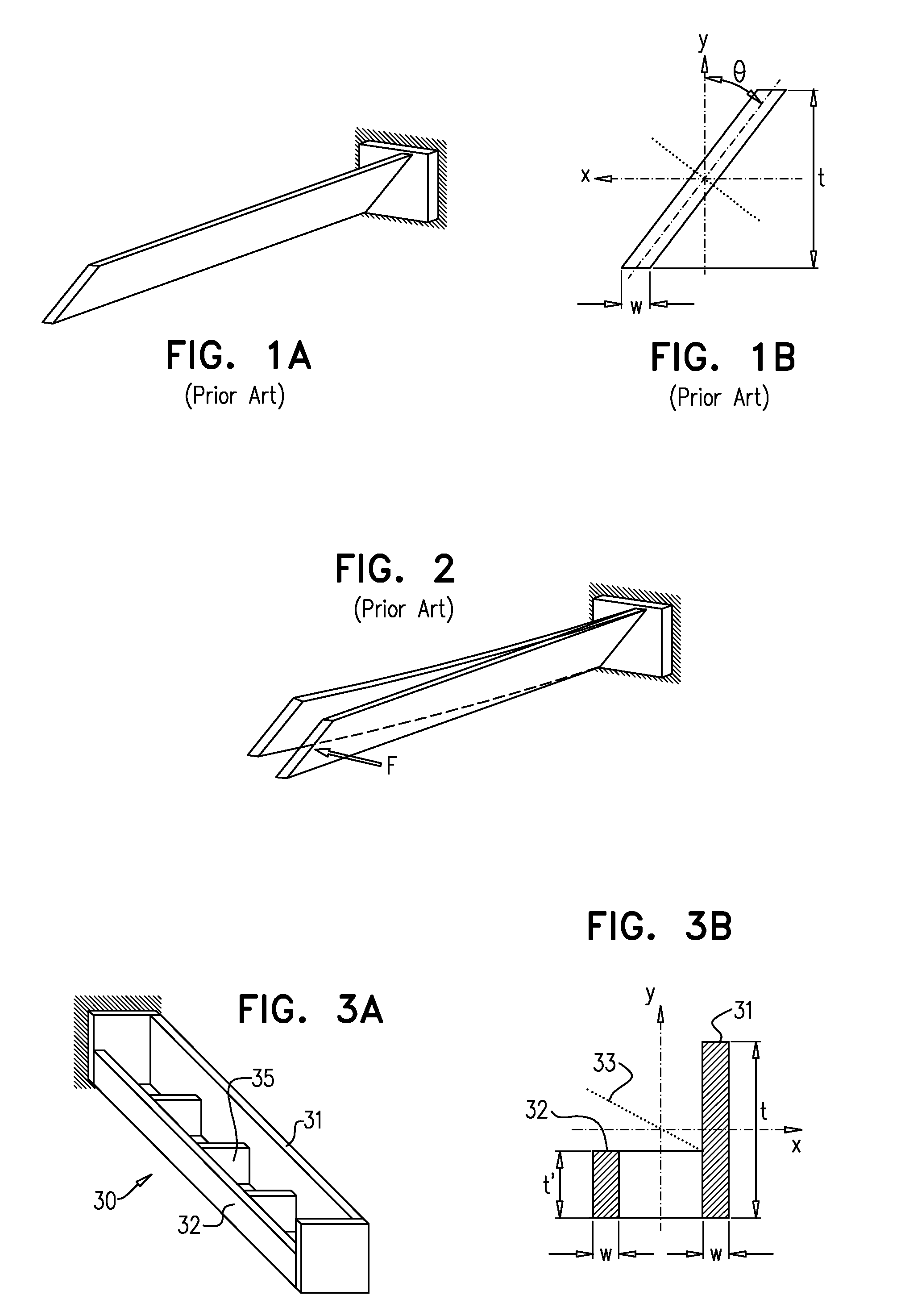
[0034]Reference is now made to FIGS. 3A and 3B, which illustrate an exemplary implementation of a dual-height cantilever double beam structure 30, which enables the generation of a vertical, out-of-plane motion from a force applied to the beam structure in an in-plane direction. FIG. 3A is an isometric view, while FIG. 3B is a cross-sectional view. The structure is significantly less complicated to fabricate than prior art structures designed to achieve this purpose, such as those described in the Background Section of this disclosure. The flexure structure 30 is constructed of two connected parallel beams with two different cross-sectional heights, a beam of greater height 31 and a beam of lesser height 32. For increased convenience and lower cost of fabrication, the height of the taller beam, marked t in FIG. 3B, could be made equal to the thickness of the wafer in which the structure is being fabricated, such that it would require no height reduction, while the height of the othe...


PUM


Abstract

A mechanism and method for motion conversion is disclosed. This mechanism can be easily fabricated using standard bulk micromachining technology. Based on this method with appropriate design, a horizontal, in-plane motion can be converted to a vertical or angular displacement out-of-plane. This design has great advantages in micro devices, which are built from a single layer, i.e. wafer fabrication, where an in-plane force is easy to implement, such as by the use of comb drive mechanisms, but an out-of-plane motion may be hard to achieve. The mechanism comprises a pair of beams of different heights, rigidly connected together at a number of points along their length, such that application of an in-plane force to the double beam structure results in out-of-plane motion of the double beam structure at points distant from the point of application of the force.

Description

RELATED APPLICATIONS[0001]The present application claims the benefit under 35 U.S.C. §119(e) of U.S. Provisional Patent Application U.S. Ser. No. 61 / 668,247, filed on Jul. 5, 2012, the contents of which is incorporated herein by reference, in its entirely.FIELD OF THE INVENTION[0002]The present invention relates to the field of micro-electromechanical system (MEMS) motion conversion mechanisms, by which a horizontally applied force can generates a vertical or an angular displacement, so that such mechanisms can convert an in-plane motion to an out-of-plane motion.BACKGROUND OF THE INVENTION[0003]When mechanisms are fabricated by patterning a single uniform material layer, such as in micromachining of micro devices, an out-of-plane mechanical displacement is often induced by using out-of-plane forces. This often requires hybrid complex assemblies, such as are described in the article by D. Elata, et al, “A Novel Tilting Micromirror with a Triangular Waveform Resonance Response and an...

Claims


Application Information

Patent Timeline
Patent Type & Authority Patents(United States)
IPC IPC(8): F16H21/44B81B3/00
CPCF16H21/44B81B3/0062B81B2201/038B81B2203/0118Y10T74/18888
Inventor ELATA, DAVIDHIRSHBERG, ARNON
Owner TECHNION RES & DEV FOUND LTD
Why Eureka
Try Eureka