
Power supply unit for electric vehicle

a technology for electric vehicles and power supply units, applied in the field of batteries, can solve the problems of low reliability of batteries, affecting the thermal uniformity of batteries, and difficulty in predetermining clearance between cells during design

Active Publication Date: 2016-04-05
BYD CO LTD
View PDF21 Cites 17 Cited by
  • Summary
  • Abstract
  • Description
  • Claims
  • Application Information

AI Technical Summary

Benefits of technology

The power supply unit for an electric vehicle described in this patent ensures that the battery module is secure and stable, even during swelling of the cells. It also ensures thermal uniformity of the battery. The battery pack can be easily disposed into the housing without rocking, which ensures reliability of the power supply unit. Overall, this technology ensures the efficient and reliable power supply for electric vehicles.

Problems solved by technology

For example, swelling of battery cells may influence reliability of the battery, such as: (1) causing the cells to move in the battery module, and thus weakening the connection between the cells; (2) causing the size of the cells to be enlarged, and thus increasing requirements for the strength of the module housing and the space occupied of the module housing; (3) causing the clearance between the cells to be difficult to predetermine during designing due to uncontrollable factors: if the clearance is too small, the cells may be difficult to be disposed into the housing or the housing may be damaged; if the clearance is too large, the cells may rock in the module; (4) causing unequal clearances between the cells due to non-uniform swelling of the cells, and thus affecting the thermal uniformity of the battery.
Since the swelling of the general battery is uncontrollable, the reliability of the battery is low.
Therefore, the reliability of the electric vehicle is low.

Method used


Image

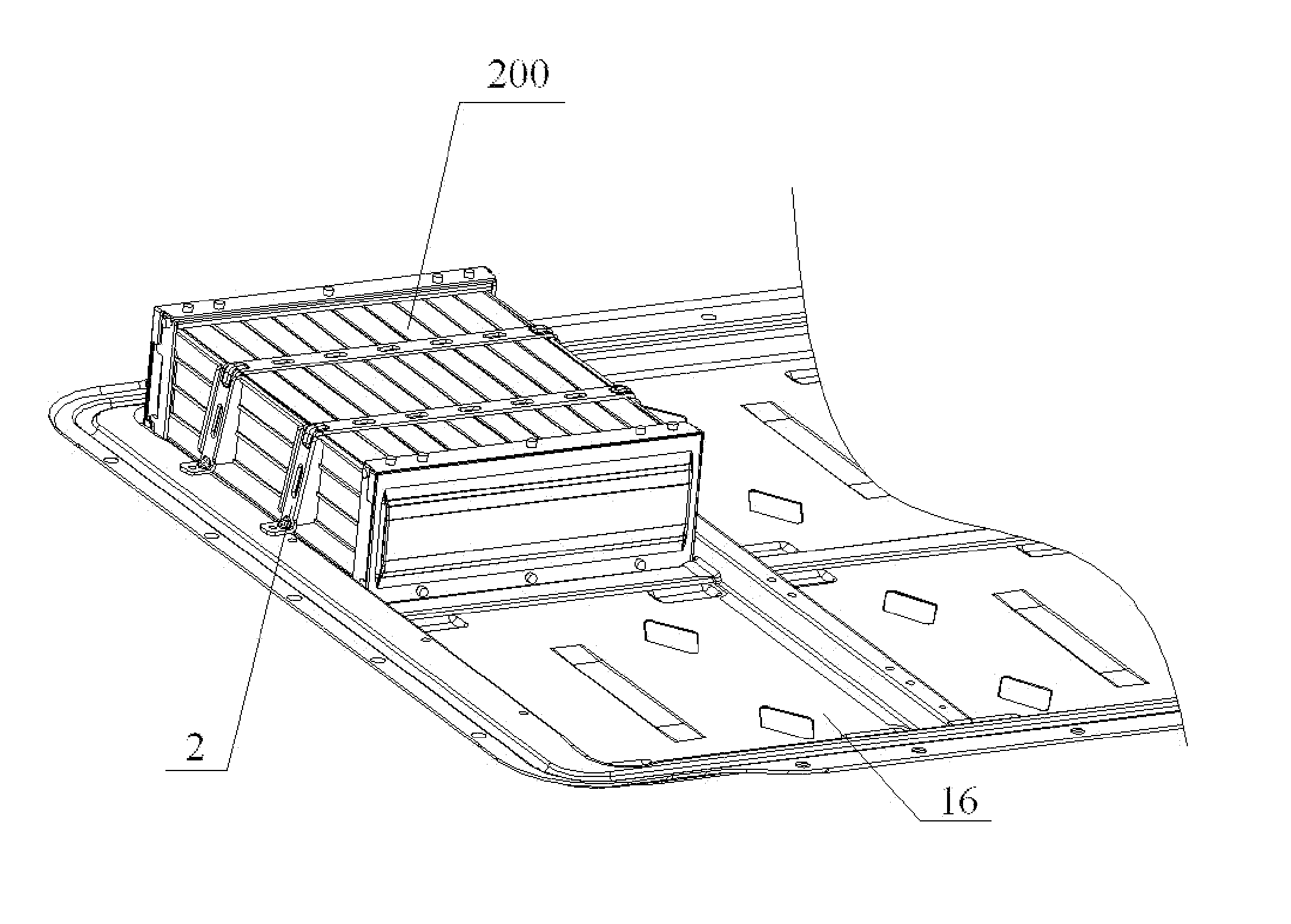
  • Power supply unit for electric vehicle
  • Power supply unit for electric vehicle
  • Power supply unit for electric vehicle

Examples


Embodiment Construction

[0013]Reference will be made in detail to embodiments of the present disclosure. The embodiments described herein with reference to drawings are explanatory, illustrative, and used to generally understand the present disclosure. The embodiments shall not be construed to limit the present disclosure. The same or similar elements and the elements having same or similar functions are denoted by like reference numerals throughout the descriptions.

[0014]In the specification, Unless specified or limited otherwise, relative terms such as “front”, “rear”, “inner”, “outer”, “up”, “top”, “bottom” as well as derivative thereof (e.g., “horizontally”, “downwardly”, “upwardly”, etc.) should be construed to refer to the orientation as then described or as shown in the drawings under discussion. These relative terms are for convenience of description and do not require that the present disclosure be constructed or operated in a particular orientation.

[0015]A power supply unit for an electric vehicl...


PUM

PropertyMeasurementUnit
flexibleaaaaaaaaaa
poweraaaaaaaaaa
swellingaaaaaaaaaa

Abstract

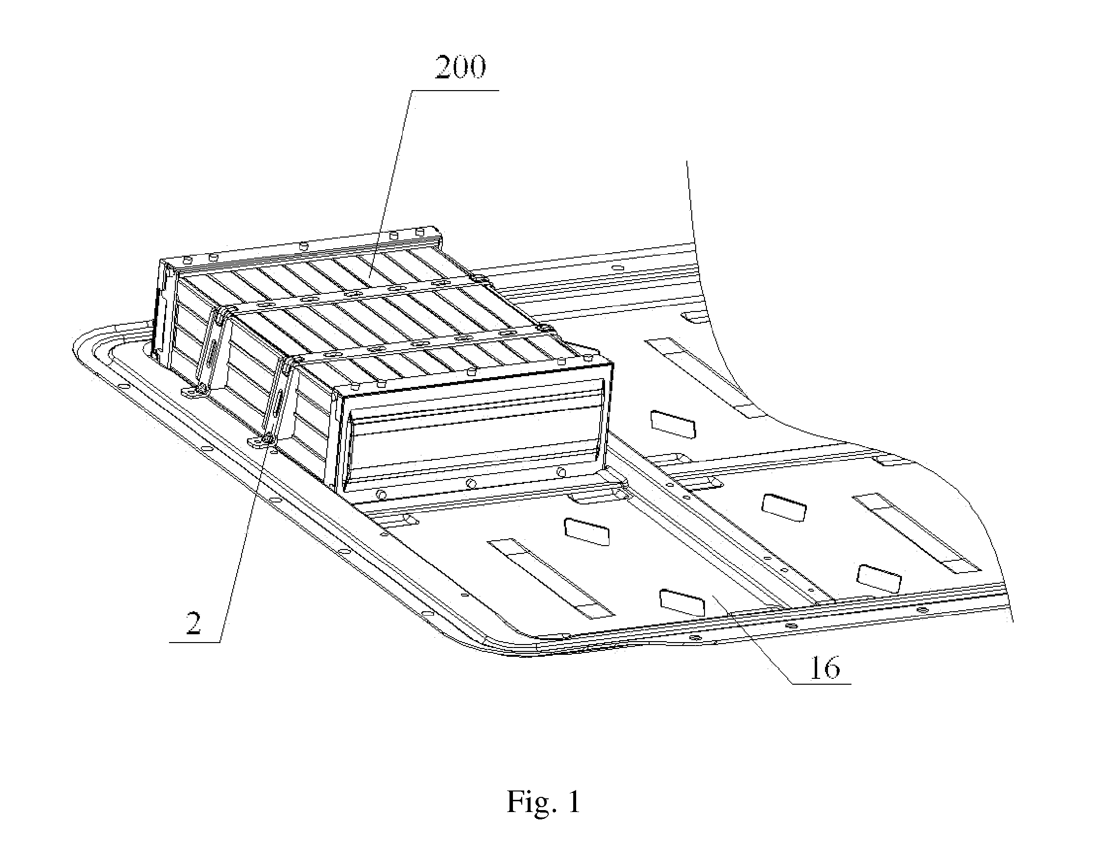
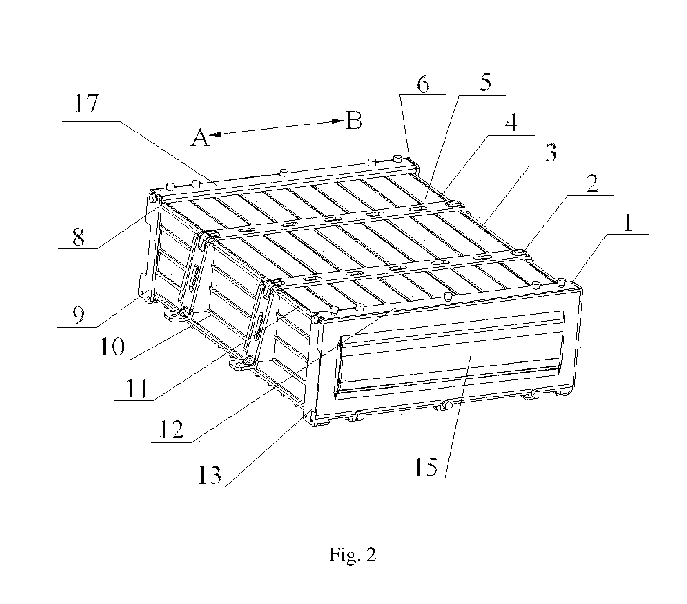
A power supply unit for an electric vehicle includes a tray and at least one battery module fixed on the tray via a strip. Each battery module includes a housing having a bottom plate mounted onto the tray, first to fourth side plates disposed on the bottom plate, a battery pack disposed in the housing and having a plurality of cells arranged along a thickness direction, and first flexible members disposed between the first side plate and the battery pack, and between the third side plate and battery pack respectively, for fastening the battery pack.

Description

CROSS REFERENCE TO RELATED APPLICATIONS[0001]This application is a continuation application of International Application No. PCT / CN2012 / 078386, filed on Jul. 9, 2012, which claims priority and benefits of Chinese Patent Application No. 201120255383.9, filed with the State Intellectual Property Office of P. R. China on Jul. 19, 2011. The entire content of above-referenced applications is incorporated herein by reference.FIELD[0002]Embodiments of the present disclosure generally relate to a technical field of battery, more particularly, to a power supply unit for an electric vehicle.BACKGROUND ART[0003]An iron battery, as an energy storage device and an important component of an electric vehicle, has significant effects on capabilities of the electric vehicle. For example, swelling of battery cells may influence reliability of the battery, such as: (1) causing the cells to move in the battery module, and thus weakening the connection between the cells; (2) causing the size of the cell...

Claims


Application Information

Patent Timeline
Patent Type & Authority Patents(United States)
IPC IPC(8): H01M2/10B60K1/04H01M50/204H01M50/227H01M50/264
CPCH01M2/1083H01M2/1077B60K1/04Y02T10/70Y02E60/10H01M50/204H01M50/264H01M50/227B60L50/66B60Y2200/91H01M2220/20
Inventor LU, JIALU, ZHIPEIZHU, JIANHUA
Owner BYD CO LTD
Learn More