Homogenizing valve

a technology of homogenizing valves and globules, applied in the direction of flow control, mixers, instruments, etc., can solve the problems of volumetric capacity oscillation, and achieve the effect of reducing the size of the globules and uniform globule siz

Active Publication Date: 2013-11-19
GEA MECHANICAL EQUIP ITAL
View PDF13 Cites 17 Cited by
  • Summary
  • Abstract
  • Description
  • Claims
  • Application Information

AI Technical Summary

Benefits of technology

[0016]The purpose of the present invention is to overcome the drawbacks described above by providing a homogenizing valve that is particularly efficient which, in other words, effectively reduces the size of the globules contained in the fluid to be homogenized while also ensuring uniformity in globule size.

Problems solved by technology

One of the reasons for this is that the width of the passage is not perfectly constant given that the infeed pump has a finite number of pistons with the result that there are oscillations in the volumetric capacity.

Method used


Image

  • Homogenizing valve
  • Homogenizing valve
  • Homogenizing valve

Examples


Embodiment Construction

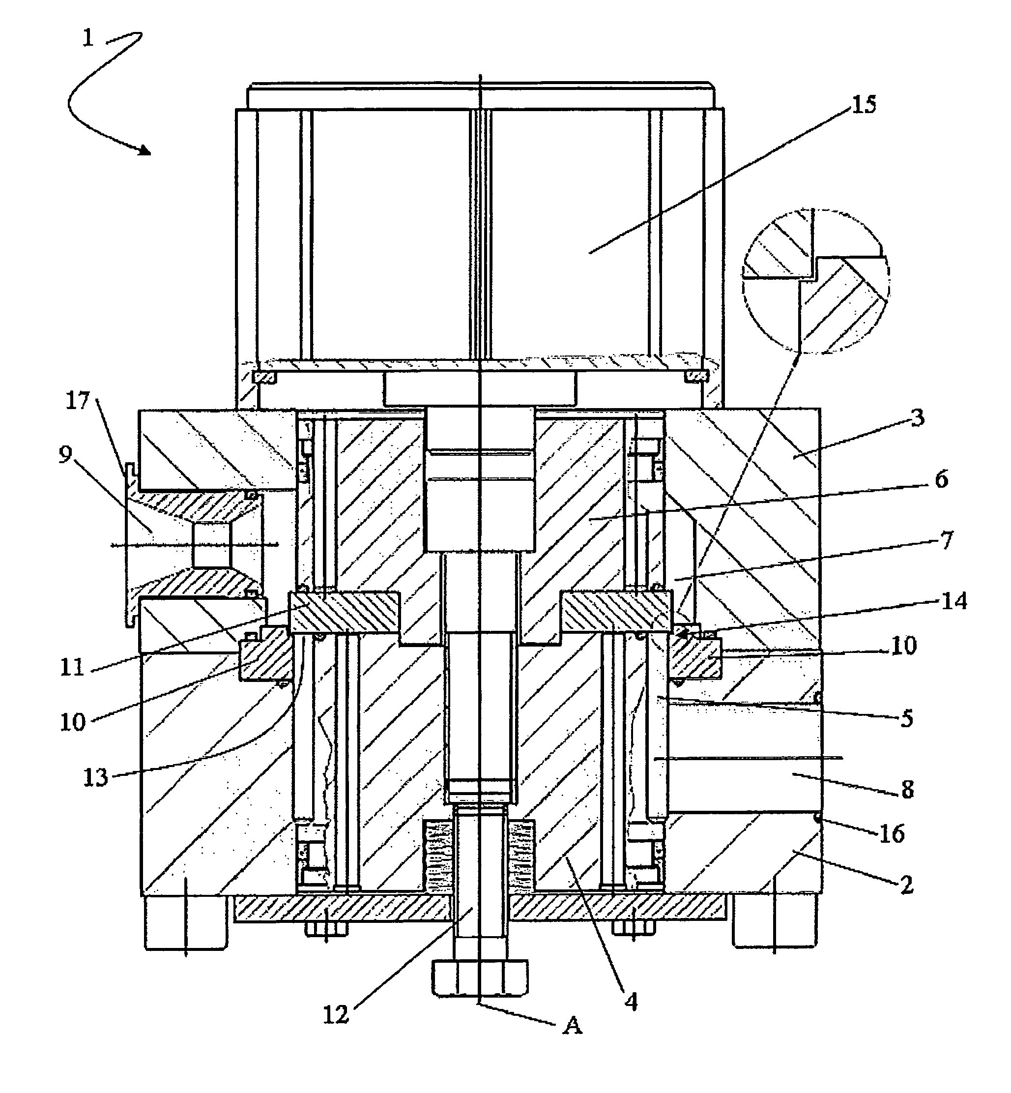
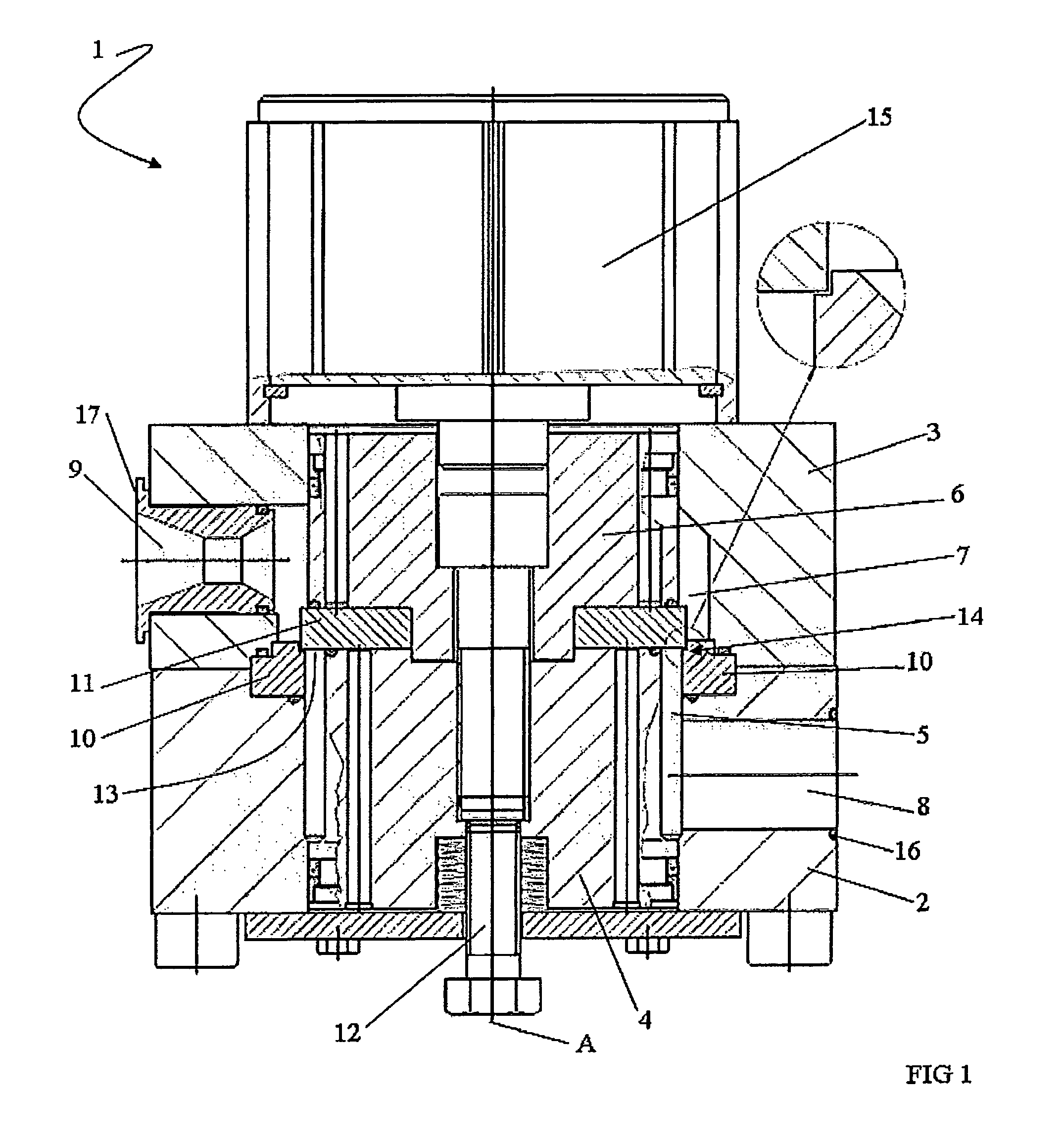
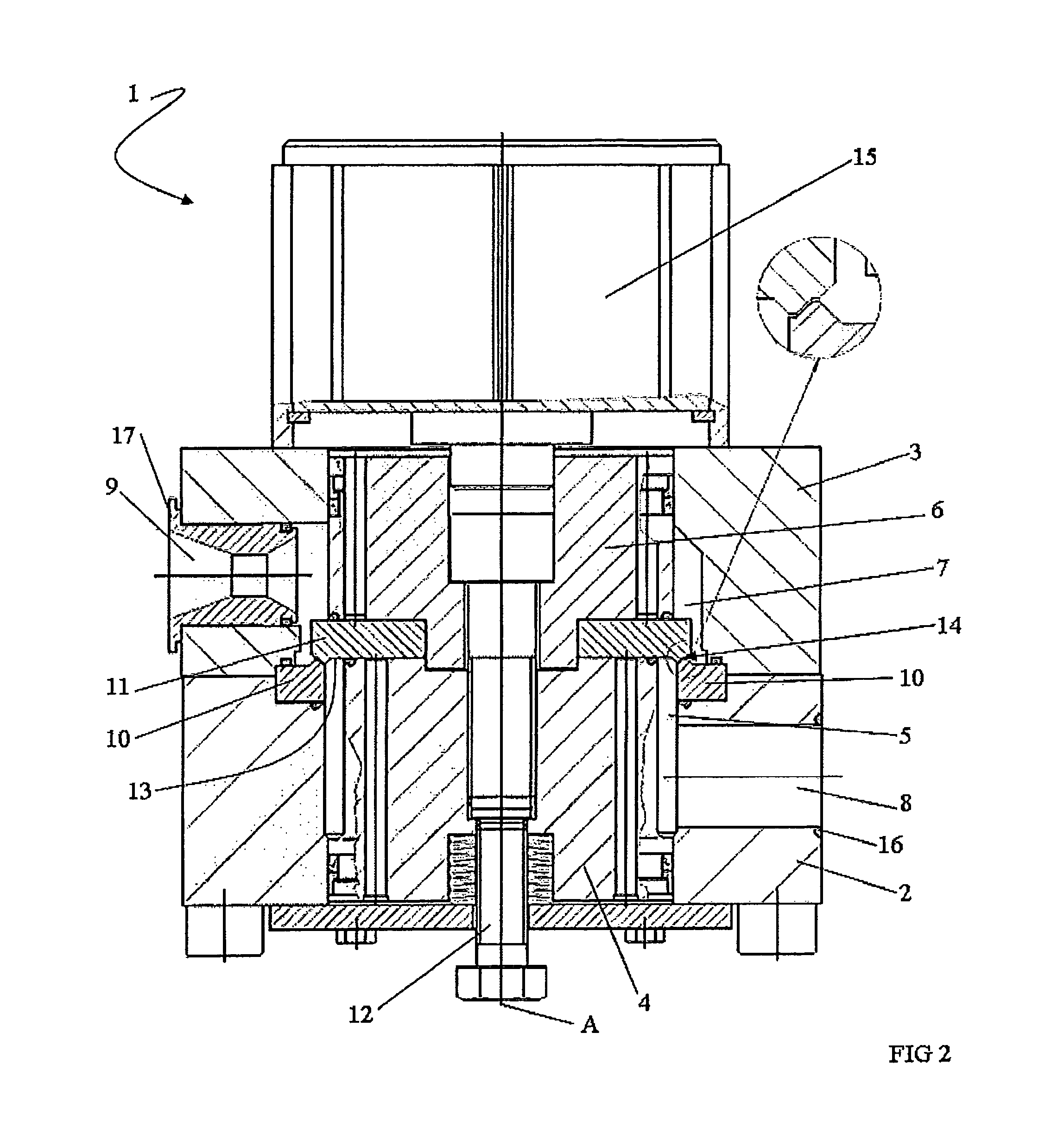
[0025]In the figures, the numeral 1 indicates a homogenizer valve according to the present invention.

[0026]The valve 1 is a homogenizing valve for the treatment of fluid products and in particular of liquids.

[0027]The valve 1 is rotation-symmetrical with a longitudinal axis A. The valve comprises a lower valve body 2 and an upper valve body 3 which are axially aligned.

[0028]Inside a hole in the lower valve body 2 there is a lower piston 4 inserted in such a way as to define a first chamber 5 which has a ring shape. The first chamber 5 extends lengthways and has a thickness defined by the difference between the radius of the hole in the lower valve body 2 and the radius of the lower piston 4.

[0029]Inside a hole in the upper valve body 3 there is an upper piston 6 inserted in such a way as to define between the upper valve body 3 and the upper piston 6 a second chamber 7 which has a ring shape. The second chamber 7 extends lengthways and has a thickness defined by the difference betwe...


PUM

PropertyMeasurementUnit
thicknessaaaaaaaaaa
thicknessaaaaaaaaaa
thicknessaaaaaaaaaa

Abstract

A homogenizer valve (1) comprising a ring-shaped first chamber (5) with an inlet (8) for receiving fluid under high pressure, a second ring-shaped chamber (7) with an outlet (9) for fluid under low pressure, a passage head (10) and, between the first and the second chamber, an impact head (11) which is axially mobile with respect to the passage head (10) and acts together with it to define a gap between the impact head (11) and the passage head (10) forming a passage (14) for the fluid passing from the first chamber to the second chamber, and a pusher (15) acting on the impact head (11) to push it in an axial direction towards the passage head (10) thus partially counteracting the pressure exerted by the fluid contained in the first chamber (5) on the annular surface (13) of the impact head (11), this passage (14) comprising at least a first portion (20) and a second portion (21) positioned in sequence between the first chamber and the second chamber, and where the first portion faces in a radial direction and the second portion faces in a direction with an axial component.

Description

TECHNICAL FIELD AND BACKGROUND ART[0001]The present invention relates to a homogenizing valve.[0002]The present invention refers in particular to equipment for homogenizing fluids and in particular liquids containing particles, globules and fibres, that is, products which are substantially liquid but subject to the formation of solid portions or otherwise liquids which have high density (such as milk containing fat globules).[0003]Homogenizing equipment comprises a high-pressure pump and a homogenizing valve with an inlet connected to the delivery port of the pump for receiving pressurized fluid and an outlet for the low-pressure homogenized fluid.[0004]The homogenization obtained in this way consists substantially of breaking up the globules in order to achieve the following objectives:[0005]to reduce the average size of the globules to the minimum;[0006]to make the globule size as uniform as possible (or, expressed in statistical terms, to reduce the variance of the amplitude dist...

Claims


Application Information

Patent Timeline
Patent Type & Authority Patents(United States)
IPC IPC(8): B01F5/06B01F25/46
CPCB01F5/0663B01F5/068B01F5/0681B01F3/0807B01F2003/125B01F2215/0006B01F23/41B01F23/56B01F25/4412B01F25/4422B01F25/4423B01F2101/07
Inventor GRANDI, SIMONEGRASSELLI, SILVIA
Owner GEA MECHANICAL EQUIP ITAL
Why Eureka
Try Eureka