Poppet valve for a compressor

a technology for compressors and poppets, which is applied in the direction of valve housings, positive displacement liquid engines, machines/engines, etc., can solve the problems of premature wear of closing elements and restricted movement of support elements in the bores

Active Publication Date: 2016-04-12
BURCKHARDT COMPRESSION AG
View PDF4 Cites 18 Cited by
  • Summary
  • Abstract
  • Description
  • Claims
  • Application Information

AI Technical Summary

Benefits of technology

[0009]The poppet valve according to the invention has the advantage that this has a passage arranged eccentrically in relation to the bore through the support element and the bottom element, so that dirt particles which penetrate the bore or between the bore and the closing element may be discharged from the bore via the eccentrically arranged passage. In a particularly advantageous embodiment, the eccentrically arranged passage is arranged in the region of the wall of the bore, which gives the advantage that the movement of the closing element transports the dirt particles in the direction towards the passage, resulting in an automatic cleaning and discharge of the contaminants from the bore. The poppet valve disclosed in publication US2010 / 0090149 in contrast has the substantial disadvantage that the impact of closing element on the support element leads to compression of the contamination on the support element due to the impacting closing element, so that the contamination accumulates on the support element and even after a relatively short operating duration, the movement of the support element in the bore is restricted. A further disadvantage is that the closing elements wear prematurely.
[0012]In a particularly advantageous embodiment, the bottom element and the support element are configured adapted to each other such that the passage is constantly open throughout. In a further advantageous embodiment, the bottom element and the support element are configured adapted to each other such that the passage is either open throughout or is closed partially or even completely, depending on the mutual positioning of the support element relative to the bottom element. In an advantageous embodiment, the support element is mounted moveably in the bore, in particular rotatably and / or displaceably in the direction of the bore. This movability of the support element in the bore may further support the discharge of contaminants from the bore. Because the passage changes depending on the mutual positioning of the support element relative to the bottom element, the passage is constantly cleaned of any deposited contaminants so that it is guaranteed that the passage does not become blocked even during long-term operation of the poppet valve.

Problems solved by technology

The poppet valve disclosed in publication US2010 / 0090149 in contrast has the substantial disadvantage that the impact of closing element on the support element leads to compression of the contamination on the support element due to the impacting closing element, so that the contamination accumulates on the support element and even after a relatively short operating duration, the movement of the support element in the bore is restricted.
A further disadvantage is that the closing elements wear prematurely.

Method used


Image

  • Poppet valve for a compressor
  • Poppet valve for a compressor
  • Poppet valve for a compressor

Examples


Embodiment Construction

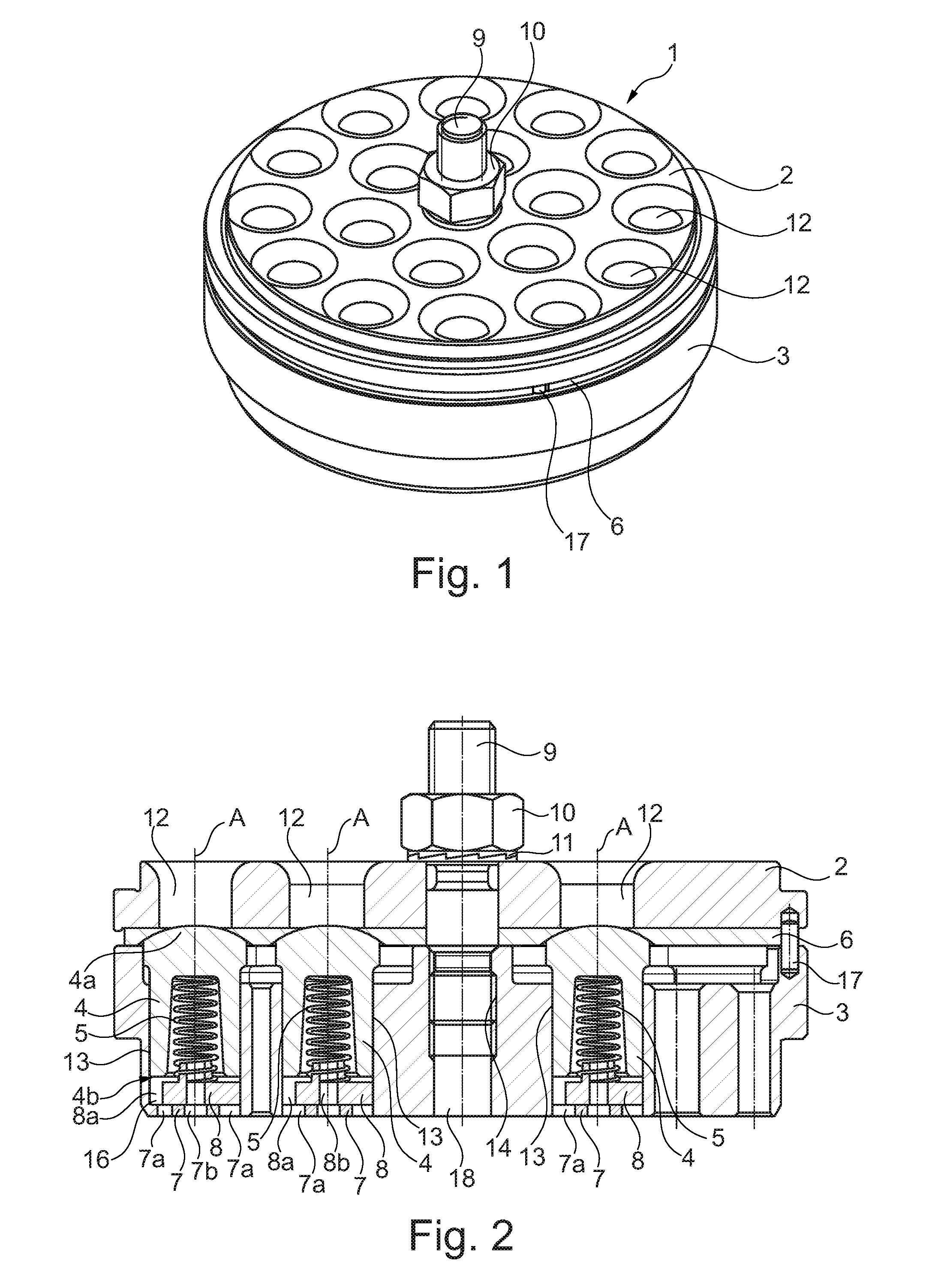
[0026]FIG. 1 shows in a perspective view a poppet valve 1 in assembled state. The poppet valve 1 comprises a valve seat 2 and a cage 3. A wearing plate 6 is arranged between the valve seat 2 and the cage 3. The cage 3 is connected to the valve seat 2 via a screw bolt 9 with nut 10. The valve seat 2 has a plurality of passage openings 12. In the present exemplary embodiment, the valve seat 2 comprises eighteen passage openings 12. A valve seat 2 may also have a different number of passage openings 12 depending on diameter and requirements.

[0027]FIG. 2 shows a longitudinal section through the poppet valve 1 shown in FIG. 1. In the exemplary embodiment shown, the wearing plate 6 is arranged between the valve seat 2 and the cage 3. In a further exemplary embodiment (not shown), the wear plate 6 may also be omitted. The cage 3 is connected to the valve seat 2 via the screw bolt 9, nut 10 and washer 11. The screw bolt 9 is held in a centrally arranged bore 18 of the cage 3 with threaded b...


PUM


Abstract

A poppet valve for a compressor, a piston compressor including such a poppet valve, and a repair kit for a poppet valve. The poppet valve has a cage, a valve seat and a plurality of closing elements, wherein the cage has a plurality of axial bores open towards the valve seat.

Description

CROSS-REFERENCE TO RELATED APPLICATION[0001]This application is the U.S. national phase of PCT Application No. PCT / EP2013 / 068093 filed on Sep. 2, 2013, which claims priority to EP Patent Application No. 12182691.1 filed on Aug. 31, 2012, the disclosures of which are incorporated in their entirety by reference herein.DESCRIPTION[0002]The invention concerns a poppet valve for a compressor, a piston compressor comprising such a poppet valve, and a repair kit for a poppet valve.BACKGROUND OF THE INVENTION[0003]Publication US2010 / 0090149 discloses a poppet valve for a compressor. This poppet valve has a cage in which a plurality of bores is produced. A closing element is arranged in each of the bores. The closing element is mushroom-shaped and has a stem and a head, the diameter of which is greater than that of the stem. The stem is held in a bore of the cage and contains a cavity in which a spring is held. At its end opposite the cavity, the spring rests on a bottom element which is arr...

Claims


Application Information

Patent Timeline
Patent Type & Authority Patents(United States)
IPC IPC(8): F16K15/08F16K27/02F04B39/10F16K15/02
CPCF04B39/1053F16K15/026F16K27/0209F04B39/1013Y10T137/7933
Inventor COLUMPSI, MICHELE
Owner BURCKHARDT COMPRESSION AG
Why Eureka
Try Eureka