
Radar sensor device having at least one planar antenna device

a technology of radar sensor and planar antenna, which is applied in the direction of individually energised antenna arrays, instruments, and reradiation, etc., can solve the problems of increasing the total cost of sensors, redundant patch antennas, and the number of mixers used as a considerable cost factor, so as to achieve minimal redundancy and good compromise

Active Publication Date: 2016-04-12
ROBERT BOSCH GMBH
View PDF9 Cites 12 Cited by
  • Summary
  • Abstract
  • Description
  • Claims
  • Application Information

AI Technical Summary

Benefits of technology

The patent text describes a way to design a radar sensor with a single-valuedness and precision of the angles while reducing the number of antenna columns and mixers. This is achieved by using sparse arrays with a minimal redundancy principle. The distance between the antenna columns is set up to achieve a minimal redundancy, with each distance present at least once but as infrequently as possible. This results in a cost reduction in the manufacturing of the radar sensor. Overall, the technical effect of the patent text is to improve the performance and reduce the manufacturing costs of radar sensors.

Problems solved by technology

Besides the size of the radar sensors, the costs of manufacturing the same are naturally also a determining factor.
Especially in planar antenna designs, where a signal evaluation is performed on the individual channels (no HF beam-forming), the number of mixers used constitutes a considerable cost factor.
If the antenna aperture is provided with a uniform linear array structure, as in previously known radar sensors, a large number of mixers is then required, thereby increasing the total costs for the sensors.
However, the patch antennas are provided redundantly, i.e., the signal relations are measured multiple times.

Method used


Image

  • Radar sensor device having at least one planar antenna device
  • Radar sensor device having at least one planar antenna device
  • Radar sensor device having at least one planar antenna device

Examples


Embodiment Construction

s

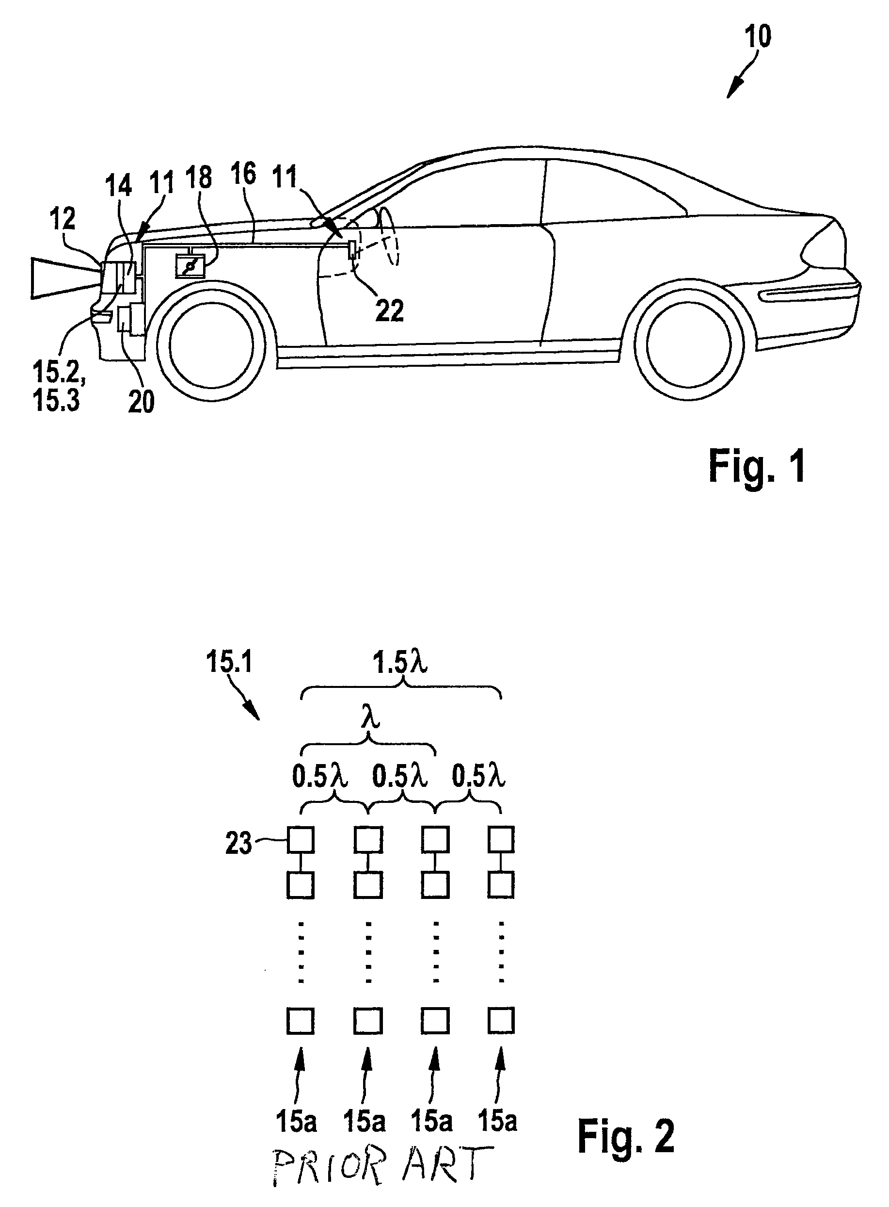
[0015]A motor vehicle 10 illustrated in FIG. 1 having an adaptive cruise control device 11 as a driver assistance system features a radar sensor device 12 as an object detection sensor which is mounted on the front end of motor vehicle 10 and in whose housing a control device 14 of adaptive cruise control device 11 is also accommodated. Radar sensor device 12 is used for detecting objects in the surrounding field of motor vehicle 10. Radar sensor device 12 is connected to control device 14. Control device 14 is connected via a data bus 16 (CAN, MOST or the like) to an electronic drive control unit 18, a brake system control unit 20, as well as to an HMI control unit 22 of a human-machine interface. In further exemplary embodiments (not shown), control unit 14 and HMI control unit 22 may also be integrated in a control device of adaptive cruise control device 12, in particular in a shared housing.

[0016]With the aid of a multi-beam radar, radar sensor device 12 measures the distances...


PUM


Abstract

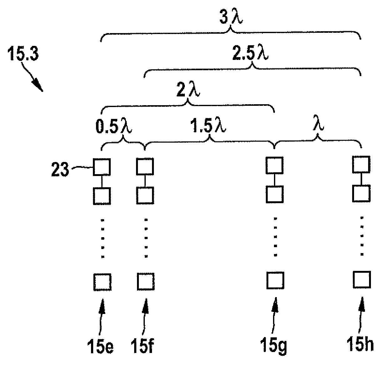
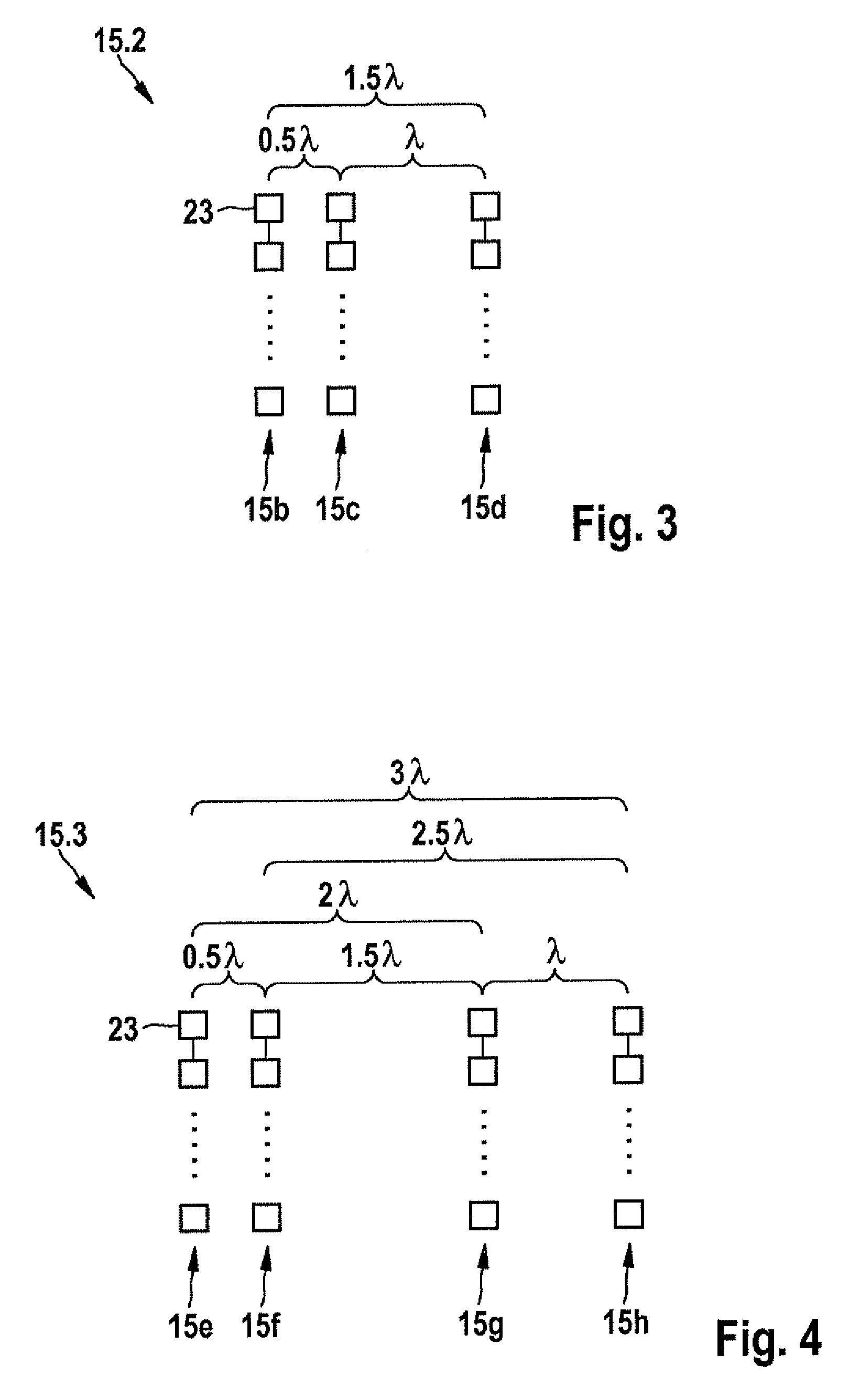
A radar sensor device having at least one planar antenna device that includes a plurality of vertically oriented antenna columns which are configured as a sparse array in one plane in parallel at defined mutual distances and which each have at least two line-fed patch elements, the sparse array of antenna columns is designed to have such a minimal redundancy that the amount of defined distances among the antenna columns in the sparse array is at least equal to all of the different distances between any two antenna columns of a corresponding non-sparse array of a planar antenna device having the same antenna aperture and the same characteristics of the antenna columns, but is the most minimum possible number.

Description

FIELD OF THE INVENTION[0001]The present invention relates to a radar sensor device having at least one planar antenna device that includes a plurality of vertically oriented antenna columns which are configured as a sparse array in one plane in parallel at defined mutual distances and which each have at least two line-fed patch elements. The present invention also relates to a device, in particular a driver assistance system of a motor vehicle.BACKGROUND INFORMATION[0002]Within the framework of driver assistance systems, radar sensors are increasingly being used in motor vehicles for sensing the traffic environment, for example, for radar-based distance control (adaptive cruise control systems / ACC). Such a cruise control system is described, for example, in “Adaptive Fahrgeschwindigkeitsregelung ACC,” (Adaptive Cruise Control ACC) yellow technical instruction series, 2002 edition by Robert Bosch GmbH.[0003]Due to the flat design and ease of manufacture thereof, for example in etchin...

Claims


Application Information

Patent Timeline
Patent Type & Authority Patents(United States)
IPC IPC(8): G01S13/93H01Q21/22H01Q1/32H01Q21/06G01S13/931
CPCG01S13/931H01Q1/3233H01Q21/065H01Q21/22G01S2013/9321G01S2013/9346G01S2013/9375G01S2013/93185G01S2013/93271
Inventor GROSS, VOLKERKUEHNLE, GOETZ
Owner ROBERT BOSCH GMBH
Learn More