Antireflection film and optical device

an anti-reflection film and optical device technology, applied in the field of anti-reflection films, can solve the problems of insufficient effect, insufficient reduction effect, easy generation of ghosts or the like, etc., and achieve the effect of high anti-reflection effect, good mechanical strength and durability of the low refractive index layer 12

Active Publication Date: 2016-04-12
TAMRON
View PDF14 Cites 9 Cited by
  • Summary
  • Abstract
  • Description
  • Claims
  • Application Information

AI Technical Summary

Benefits of technology

[0026]According to the present invention, the antireflection film excellent in antireflection characteristics against a light beam having a wide wavelength range at a wide range of an incident angle, and also having practically sufficient durability can be provided by making the antireflection film comprise the two-layer structure composed of the low refractive index layer obtained by binding the hollow silica by the binder and having a refractive index n(1) of 1.15 to 1.24 inclusive, and the intermediate layer having the refractive index n(2) that satisfies the relation in the expression (1) assuming a refractive index of the base material n(sub).

Problems solved by technology

As a result, ghost or the like is easily generated due to reflection at the lens peripheral portion.
Thus, such antireflection film cannot achieve a sufficient antireflection effect against a light beam having a wider wavelength range at a wider range of an incident angle, and insufficient effect on reduction of a ghost or the like may be supposed.
Moreover, the shape or the property of the base material may be affected by heat because a firing process at 300° C. or more is required to form the porous layer of mesoporous nanosilica.
When porous layer of the silica aerogel is formed to have a refractive index of 1.15 on the surface of a SiO2 layer as the dense layer, drawback that durability in a practical use cannot be achieved due to the inherent property of silica aerogel may occur.

Method used


Image

  • Antireflection film and optical device
  • Antireflection film and optical device
  • Antireflection film and optical device

Examples


example 1

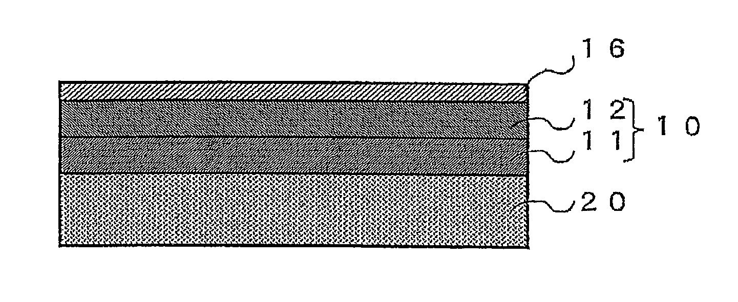
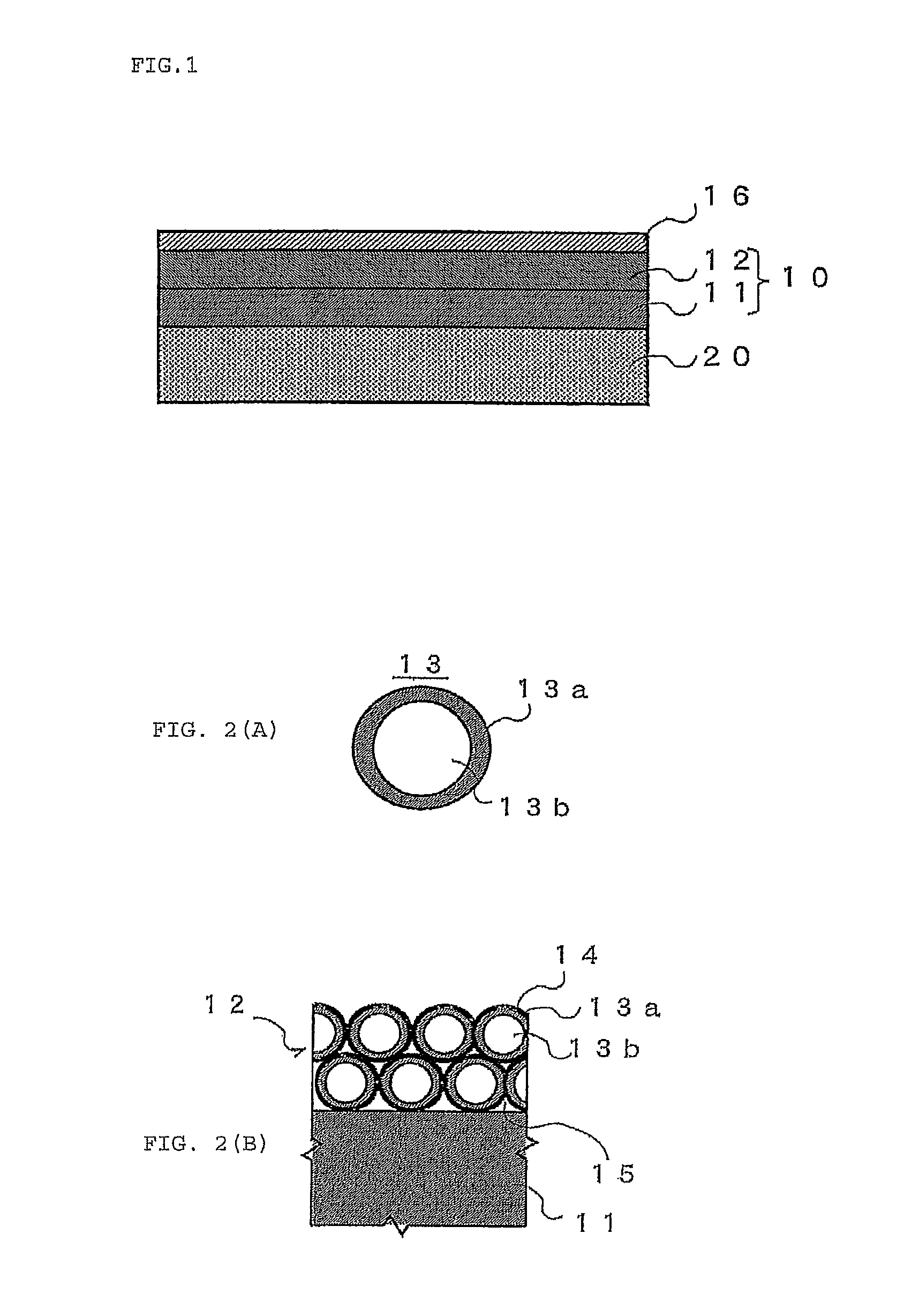
[0074]In the Example 1, a lens made of N-LAK14 glass manufactured by SCHOTT AG corp. was used as a base material 20. The antireflection film 10 having a structure shown in Table 1 was provided on the surface of the base material 20. Specifically, the intermediate layer 11 made of SiO2 was provided on the surface of the base material 20 with a thickness of 90 nm by vacuum vapor deposition using BMC1300 manufactured by Shincron Co., Ltd. Note that the intermediate layer 11 was not a layer formed by using the hollow silica 13, but was a vapor deposited layer of SiO2 (in the following, the term SiO2 means SiO2 without a hollow structure.).

[0075]Next, a coating solution prepared by dissolving an acrylic resin as the binder component in a solvent and suspending the hollow silica 13 was used to form the low refractive index layer 12 on the surface of the intermediate layer 11 by spin coating using MS-A150 manufactured by Mikasa Co, Ltd. Then, the low refractive index layer 12 was heated at...

example 2

[0079]In the Example 2, the same base material 20 as that in the Example 1 was used, and the antireflection film 10 was provided on the base material 20 in a similar manner to Example 1 except that the intermediate layer 11 was replaced with a PMMA resin layer having a physical film thickness of 89 nm and an optical film thickness of 134 nm. As the intermediate layer 11, a coating solution prepared by dissolving acrylic resin in propylene glycol monomethyl acetate as a solvent was used to form the PMMA resin film on the base material 20 by spin coating. Table 2 shows the layer structure of the antireflection film 10 prepared in the present Example 2 and the refractive indexes of the respective layers. Based on the expression (1), and refractive indexes n(1) of the low refractive index layer 12 and n(sub) of the base material 20, preferable refractive index n(2) of the intermediate layer 11 is in a range of 1.45≦n(2)≦1.54. As shown in Table 2, the refractive index n(2) of the interme...

example 3

[0081]In the Example 3, the same base material 20 as that in the Example 1 was used, and the antireflection film 10 was provided on the base material 20 in a similar manner to Example 1 except that a three-layer equivalent stack was employed as the intermediate layer 11. Table 3 shows the structure of the three-layer equivalent stack in the present example 3. The three-layer equivalent stack was formed such that each layer having a film thickness shown in Table 3 were provided by vacuum vapor deposition using BMC1300 manufactured by Shincron Co., Ltd. Based on the expression (1), and refractive indexes n(1) of the low refractive index layer 12 and n(sub) of the base material 20, preferable refractive index n(2) of the intermediate layer 11 is in a range of 1.45≦n(2)≦1.54. The effective refractive index n(2) of the three-layer equivalent stack as the intermediate layer 11 shown in Table 3 was 1.50.

[0082]

TABLE 3FilmOptical filmRefractivethicknessthicknessMaterialindex (n)(d) (nm)(nd) ...


PUM

PropertyMeasurementUnit
wavelengthaaaaaaaaaa
reflectanceaaaaaaaaaa
incident angleaaaaaaaaaa

Abstract

An object of the present invention is to provide an antireflection film and an optical device having excellent antireflection characteristics against a light beam having a wide wavelength range at a wide range of an incident angle, and also having practically sufficient durability. To achieve the above object, the present invention adopts an antireflection film having an optical two-layer structure composed of an intermediate layer provided on a base material and a low refractive index layer provided on a surface of the intermediate layer, wherein the low refractive index layer is a layer obtained by binding hollow silica by a binder, a refractive index n(1) thereof is between 1.15 and 1.24 inclusive, and a refractive index n(2) of the intermediate layer satisfies a relation in the expression (1) below assuming a refractive index of the base material n(sub).n(1)×√{square root over (n(sub))}×0.930≦n(2)≦n(1)×√{square root over (n(sub))}×0.985  (1).

Description

BACKGROUND OF THE INVENTION[0001]1. Field of the Invention[0002]The present invention relates to an antireflection film provided on the surface of a base material, and more particularly, to an antireflection film and an optical device having excellent antireflection characteristics against a light beam having a wide wavelength range at a wide range of an incident angle.[0003]2. Description of the Related Art[0004]Antireflection films are provided on the surfaces of the base materials for an optical device such as a lens, a prism or the like constituting optical equipments to improve a transmittance of a light. Most of conventional optical equipments have been equipment suitable to a visible range light beam incident at a particular narrow range of an incident angle. Thus, the antireflection films provided on the optical devices have been designed to perform an excellent antireflection effect at the particular narrow range of an incident angle.[0005]However, optical equipments applic...

Claims


Application Information

Patent Timeline
Patent Type & Authority Patents(United States)
IPC IPC(8): B32B3/26B32B7/02G02B1/11B32B5/16G02B1/111G02B1/14G02B1/18
CPCG02B1/11Y10T428/24942
Inventor SHIBUYA, MINORUKUNISADA, TERUFUSAYAMASHITA, NAOKI
Owner TAMRON
Why Eureka
Try Eureka