
Dual stage actuated suspension having adhesive overflow control channels

a technology of control channel and actuation suspension, which is applied in the direction of magnetic recording, data recording, instruments, etc., can solve the problems of affecting the stiffness of gimbals, degrading the static attitude attribution of the head suspension assembly, and degrading the stroke length of the microactuator

Active Publication Date: 2016-04-12
MAGNECOMP
View PDF10 Cites 23 Cited by
  • Summary
  • Abstract
  • Description
  • Claims
  • Application Information

AI Technical Summary

Benefits of technology

The technical effect of this patent is that it minimizes and controls the flow of excess adhesive, which improves the performance of the head suspension assembly and its related components. It can be difficult to dispense epoxy and control its flow, but the invention provides a solution to this problem.

Problems solved by technology

Adhesive flowing too far and / or unrepeatably can degrade the static attitude attributions of the head suspension assembly, affect the dynamic resonance attributes of it, create variations in the gram load attributes in it, affect the gimbal stiffness, and degrade the stroke length of the microactuator.

Method used


Image

  • Dual stage actuated suspension having adhesive overflow control channels
  • Dual stage actuated suspension having adhesive overflow control channels
  • Dual stage actuated suspension having adhesive overflow control channels

Examples


second embodiment

[0031]FIG. 8 is a top plan view of a suspension according to the invention. In this embodiment, adhesive overflow channel 43 leads to a reservoir 50 that is wider than the channel and is located closer to the longitudinal axis L-L of the suspension than its associated PZT. Adhesive overflow channel 43 is thus in fluid communication with the reservoir 50. In this embodiment reservoir 50 is a central reservoir that is located on the longitudinal axis L-L of the suspension, and is connected to a first adhesive overflow channel associated with the first PZT and is also connected to a second adhesive overflow channel associated with the second PZT. In this way, excess epoxy from the area of both PZTs will be channeled to central reservoir 50. Because excess epoxy is channeled to a centrally located reservoir, the suspension will be more evenly mass balanced about the longitudinal axis than if the overflow epoxy associated with one of the PZTs all stayed on the lateral side of the suspens...

third embodiment

[0032]FIG. 9 is a top plan view of a suspension according to the invention. In this embodiment adhesive overflow channels 43 are not of uniform width. Instead, the channels widen in the direction in which it is desired to direct the adhesive overflow, in this case, to a reservoir that is centrally located relative to the longitudinal axis of the suspension, and is located laterally between the two microactuators. The widths of the channels may be smoothly tapered (widening) toward the central longitudinal axis. Selectively widening and narrowing the channel allows the overflow adhesive to be more effectively channeled into a desired area, due to the surface tension of the adhesive which tends to draw the adhesive from the narrower portion(s) of the channel into the wider portion(s) of the channel. The channel geometry including the width of the channel and the angle of the channel walls relative to parallel (i.e., the transition slope of the channel) can be adjusted depending on the...


PUM

PropertyMeasurementUnit
areaaaaaaaaaaa
widthaaaaaaaaaa
conductiveaaaaaaaaaa

Abstract

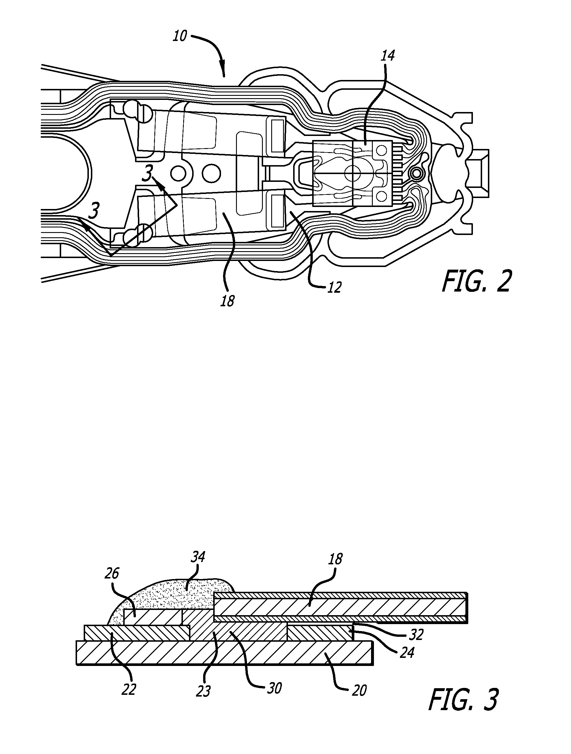
A dual stage actuated suspension has microactuators that are adhered to the suspension by adhesive such as epoxy. The epoxy is contained within an adhesive containment vessel defined by walls of an insulating material such as polyimide. Adhesive overflow channels are formed within the polyimide to receive and channel any excess epoxy that overflows over the polyimide wall. The channels may have increasing width to help draw the excess epoxy toward a centrally located reservoir.

Description

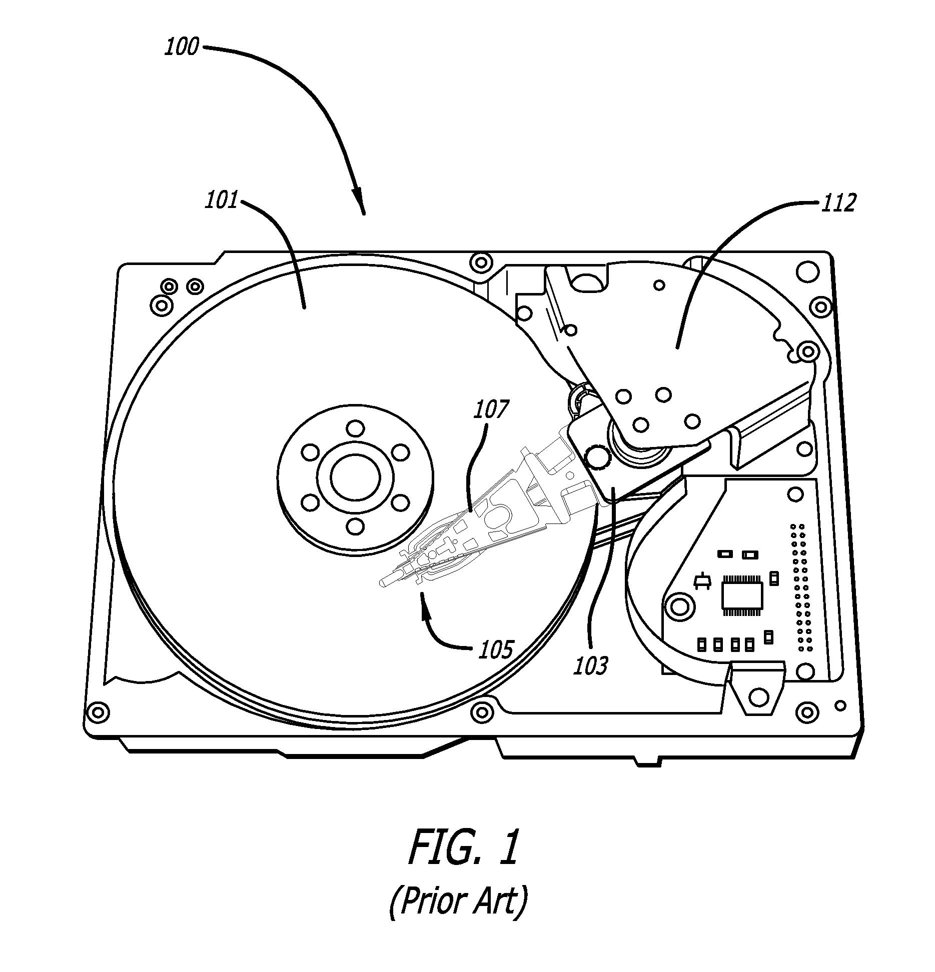
CROSS-REFERENCE TO RELATED APPLICATIONS[0001]This application claims priority from U.S. provisional patent application Ser. No. 61 / 829,167 filed May 30, 2013.BACKGROUND OF THE INVENTION[0002]1. Field of the Invention[0003]This invention relates to the field of dual stage actuated suspensions for hard disk drives. More particularly, this invention relates to the field a dual stage actuated suspension having channels to control the overflow of adhesive used to affix microactuators to the suspension.[0004]2. Description of Related Art[0005]Magnetic hard disk drives and other types of spinning media drives such as optical disk drives are well known. FIG. 1 is an oblique view of an exemplary prior art hard disk drive and suspension for which the present invention is applicable. The prior art disk drive unit 100 includes a spinning magnetic disk 101 containing a pattern of magnetic ones and zeroes on it that constitutes the data stored on the disk drive. The magnetic disk is driven by a d...

Claims


Application Information

Patent Timeline
Patent Type & Authority Patents(United States)
IPC IPC(8): G11B5/48
CPCG11B5/483G11B5/4826G11B5/48G11B5/4853G11B5/486
Inventor EE, KUEN CHEEHAHN, PETERZHANG, LONGMANGOLD, MARKUS ERWIN
Owner MAGNECOMP
Learn More