
Ion ejection from a quadrupole ion trap

a quadrupole ion trap and ejection technology, applied in the field of ion ejectors, can solve the problem of inability to reduce these potentials to near zero, and achieve the effect of reducing the initial velocity spread and high mass resolving power

Active Publication Date: 2016-04-12
THERMO FISHER SCI BREMEN
View PDF18 Cites 11 Cited by
  • Summary
  • Abstract
  • Description
  • Claims
  • Application Information

AI Technical Summary

Benefits of technology

[0028]It is desirable to eject ions from the quadrupole ion trap in a way which minimises the velocity spread in a preferred direction. The preferred direction may be generally in the direction of an analyser injection trajectory in embodiments in which the quadrupole ion trap ejects ions directly into the analyser. Alternatively the preferred direction may be substantially orthogonal to the analyser injection trajectory in embodiments in which the quadrupole ion trap ejects ions into an orthogonal ejector, and ions are ejected from the orthogonal ejector into the mass analyser. As will be appreciated, ions may be deflected through an angle after they leave the quadrupole ion trap so that they then enter an analyser along an injection trajectory, or so that they enter an orthogonal ejector, in which case the preferred direction may be inclined at an angle to the injection trajectory or inclined at an angle to the orthogonal of the injection trajectory respectively.
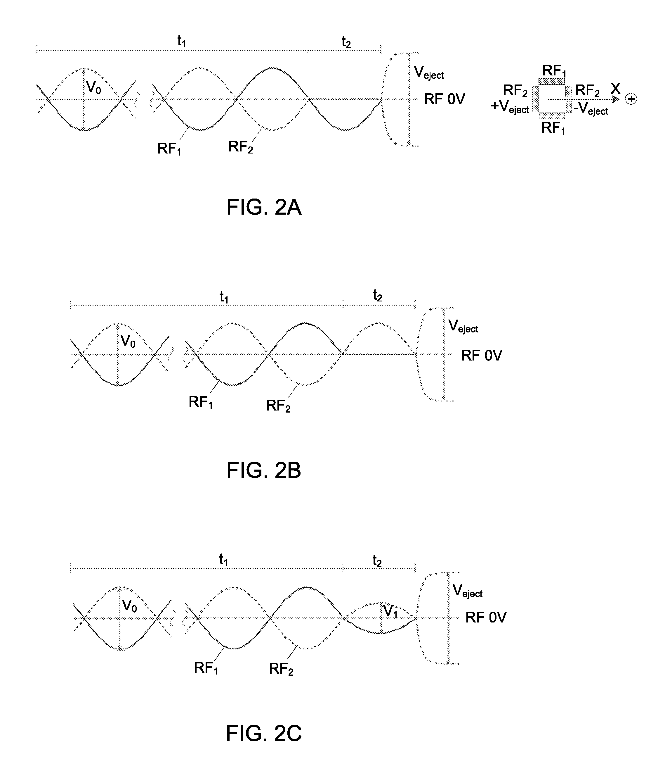
[0032]By choosing the zero crossing point to initiate the reduction in RF amplitude, the ions extracted possess a minimum velocity spread in a preferred direction and the preferred direction (x or y) may be chosen. A mixture of ions with different m / z ratios is normally present in an RF ion trap and all are extracted simultaneously. Advantageously, ions of a wide range of m / z retain their minimum velocity spreads almost at the same time, namely when the one or more RF trapping potentials reach the next zero crossing point, one half cycle after the amplitudes of the one or more RF voltages were reduced. This allows reduction of the turn-around time for all types of ion species stored in the RF quadrupole trap, with the Mathieu equation Q-parameter spanning from Qmin≈0.01 to Qmax≈0.901, the minimum value corresponding to the practical minimum of the ponderomotive force and the maximum value corresponding to the low-mass limit of the stability region.
[0044]The present invention provides an ion packet comprising ions with lower velocity spreads in a preferred direction immediately prior to ejection. Upon ejection, such an ejected ion packet may enable a higher mass resolving power to be achieved in a subsequent step of mass analysis due to the reduced initial velocity spread. Advantageously, the ions may be ejected from the trap in a process in which one or more RF trapping voltages are terminated when they reach a zero crossing point, overcoming the practical difficulties suffered by prior art arrangements in which it is practically very difficult to terminate rapidly RF trapping voltages when they are at their maximum amplitudes.

Problems solved by technology

The maximum amplitude of the RF trapping potentials may be thousands of volts and as noted above it is impractical to reduce these potentials to near zero within a very short timescale (i.e. much less than one RF cycle) due to the capacitance of the trap electrodes and associated electronic circuitry.

Method used


Image

  • Ion ejection from a quadrupole ion trap
  • Ion ejection from a quadrupole ion trap
  • Ion ejection from a quadrupole ion trap

Examples


Embodiment Construction

[0053]Various embodiments of the present invention will now be described by way of the following examples and the accompanying figures.

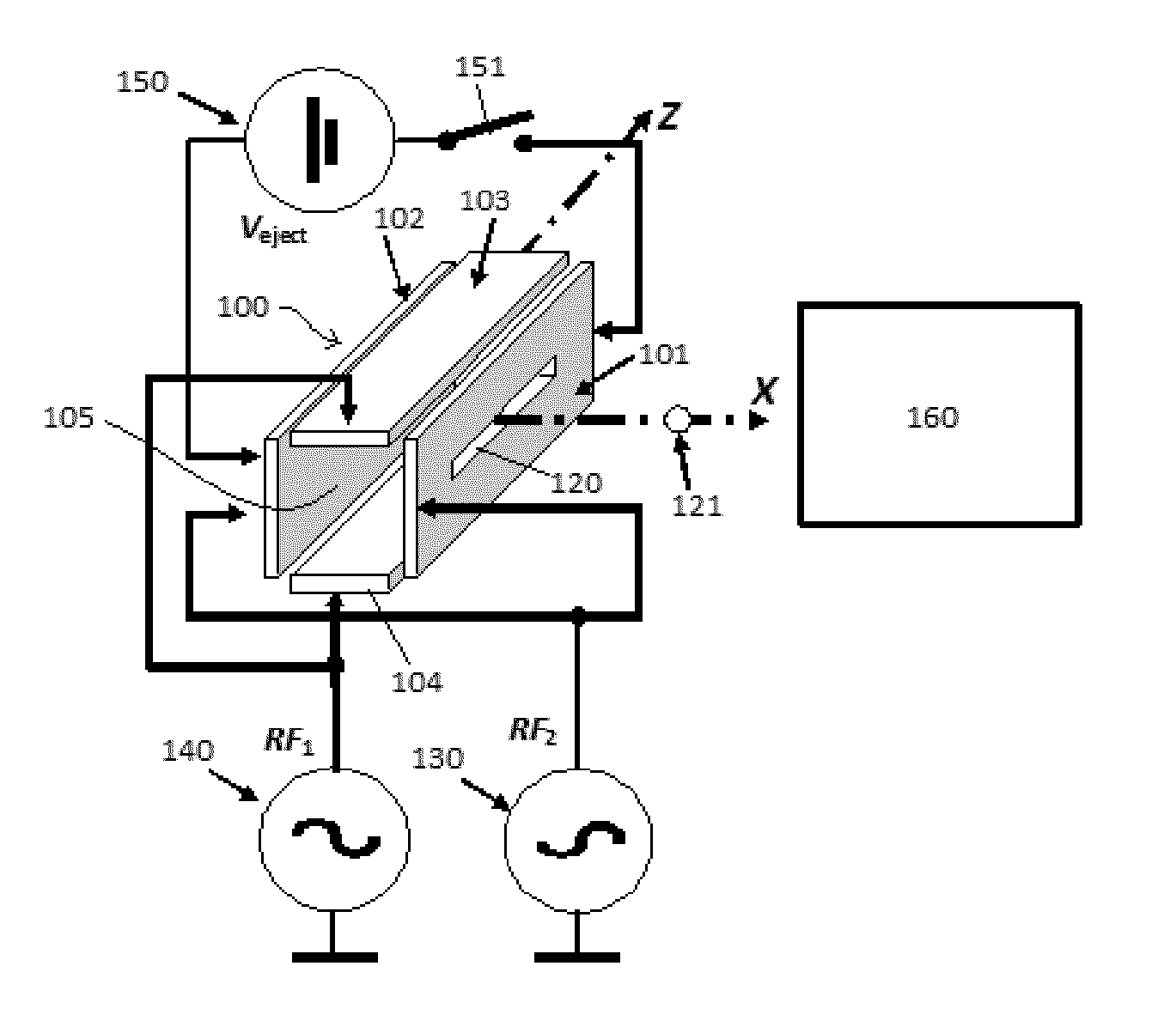
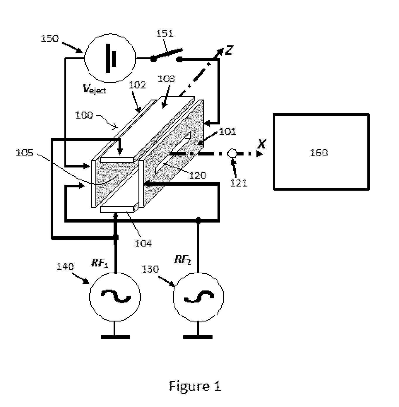
[0054]FIG. 1 shows a schematic perspective view of a linear quadrupole ion trap for use with the present invention. The trap 100 comprises four electrodes, 101, 102, 103, 104. Electrodes 101 and 102 oppose one another in the X direction, and electrodes 103, 104 oppose one another in the Y direction. Electrodes 101 and 102 are oriented perpendicular to electrodes 103 and 104. Electrodes 101, 102, 103, 104 are shown as flat plates each having a length oriented parallel to axis Z, but may be round rods each with an axis parallel with axis Z. Alternatively the electrodes may comprise hyperbolic surfaces facing in towards axis Z. Other electrode shapes are contemplated. Electrode 101 has a slot 120 for ejection of ions 121 from the trap 100 in the X direction towards mass spectrometer 160, which may be a TOF mass spectrometer, or a FT mass spectrometer, o...


PUM


Abstract

A method of ejecting ions to be analyzed from a quadrupole ion trap in which a trapping field is created by one or more RF voltages applied to one or more electrodes of the trap, the method comprising the steps of cooling the ions to be analyzed within the quadrupole ion trap until the ions are thermalized, reducing the amplitude of one or more RF voltages applied to the quadrupole ion trap and applying the reduced amplitude RF voltages for one half cycle after the one or more RF voltages have reached a zero crossing point, turning off the RF voltages applied to the quadrupole ion trap, and ejecting the ions to be analyzed from the quadrupole ion trap.

Description

FIELD OF THE INVENTION[0001]This invention relates to the field of ion ejectors for providing pulsed ion packets to time-of-flight mass analysers, ion trap mass analysers or Fourier Transform mass analysers. In particular the invention relates to ion ejectors which comprise quadrupole ion traps.BACKGROUND OF THE INVENTION[0002]Quadrupole ion traps operated with radio-frequency (RF) potentials (also known as Paul traps) are used in mass spectrometry for accumulating ions and for ejecting pulsed packets of ions into a mass analyser. Suitable mass analysers include time-of-flight (TOF), electrostatic trap (EST), and Fourier Transform mass spectrometers (FT-MS). TOF mass spectrometers include linear TOF, reflectron TOF and multireflection TOF. EST mass spectrometers include orbital traps such as Kingdon traps, a type of which is marketed as ORBITRAP™ by the applicant and which utilises image current ion detection and Fourier Transform signal processing. FT-MS mass spectrometers include ...

Claims


Application Information

Patent Timeline
Patent Type & Authority Patents(United States)
IPC IPC(8): H01J49/00H01J49/42H01J49/40H01J49/04H01J49/06H01J49/28
CPCH01J49/4225H01J49/0481H01J49/0031H01J49/282H01J49/427H01J49/063H01J49/424H01J49/40H01J49/4245
Inventor HOCK, CHRISTIAN ALBRECHTGRINFELD, DMITRYHEMING, RICHARD
Owner THERMO FISHER SCI BREMEN
Learn More