
Technique for localizing sound source

a technology for localizing sound sources and sound fields, applied in static indicating devices, loudspeakers, instruments, etc., can solve the problems of reducing resolution, limiting the localization of low frequency noise sources, and inevitably forming delay-sum beam forming techniques, so as to improve the resolution of sound field visualization, reduce measurement frequency and time, and reduce the amount of calculation

Active Publication Date: 2016-04-19
HYUNDAI MOTOR CO LTD
View PDF16 Cites 7 Cited by
  • Summary
  • Abstract
  • Description
  • Claims
  • Application Information

AI Technical Summary

Benefits of technology

The present invention provides a way to find the source of a sound and estimate the pressure of the sound waves in relation to low-frequency noise. It also improves the clarity of sound field visualization by making it easier to identify the position of the sound source. Compared to traditional methods, this invention reduces the time and effort required for sound source localization.

Problems solved by technology

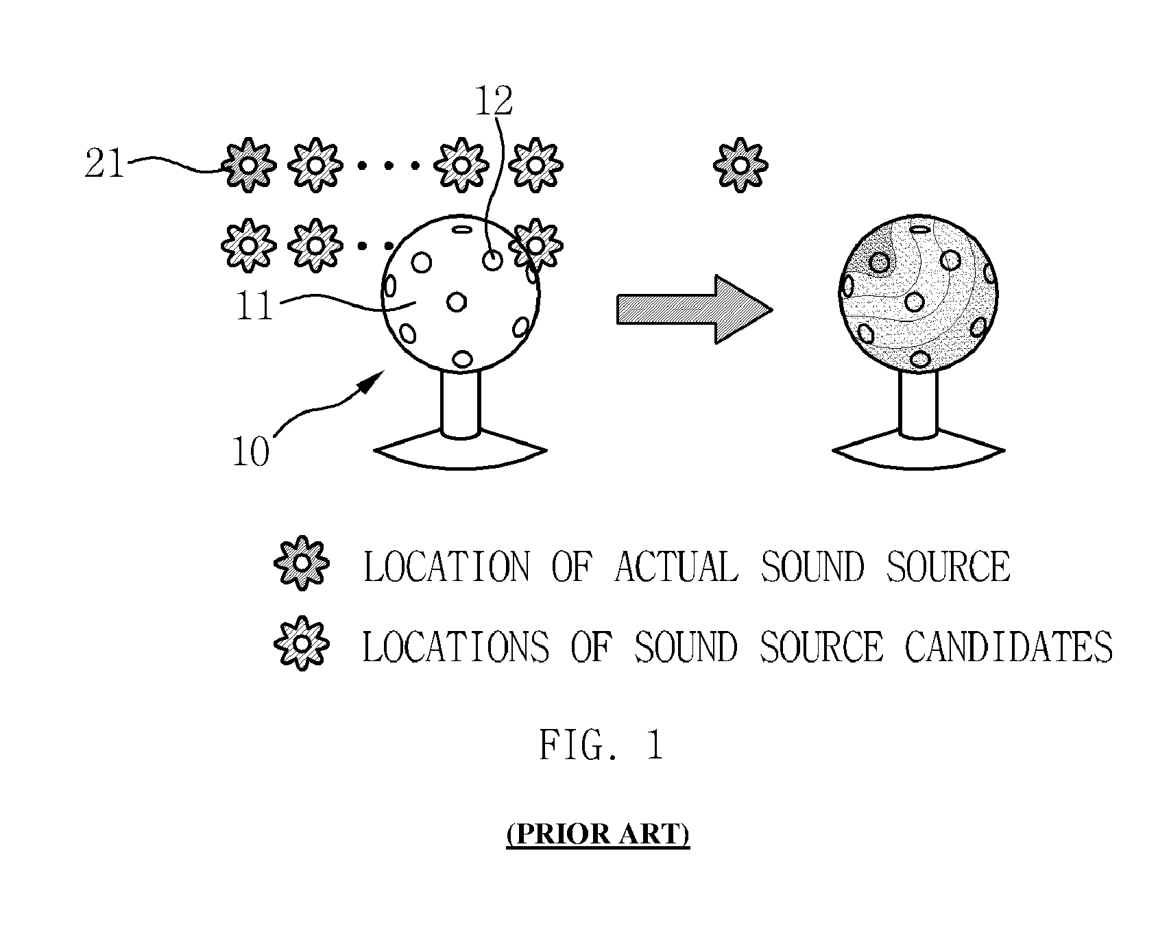
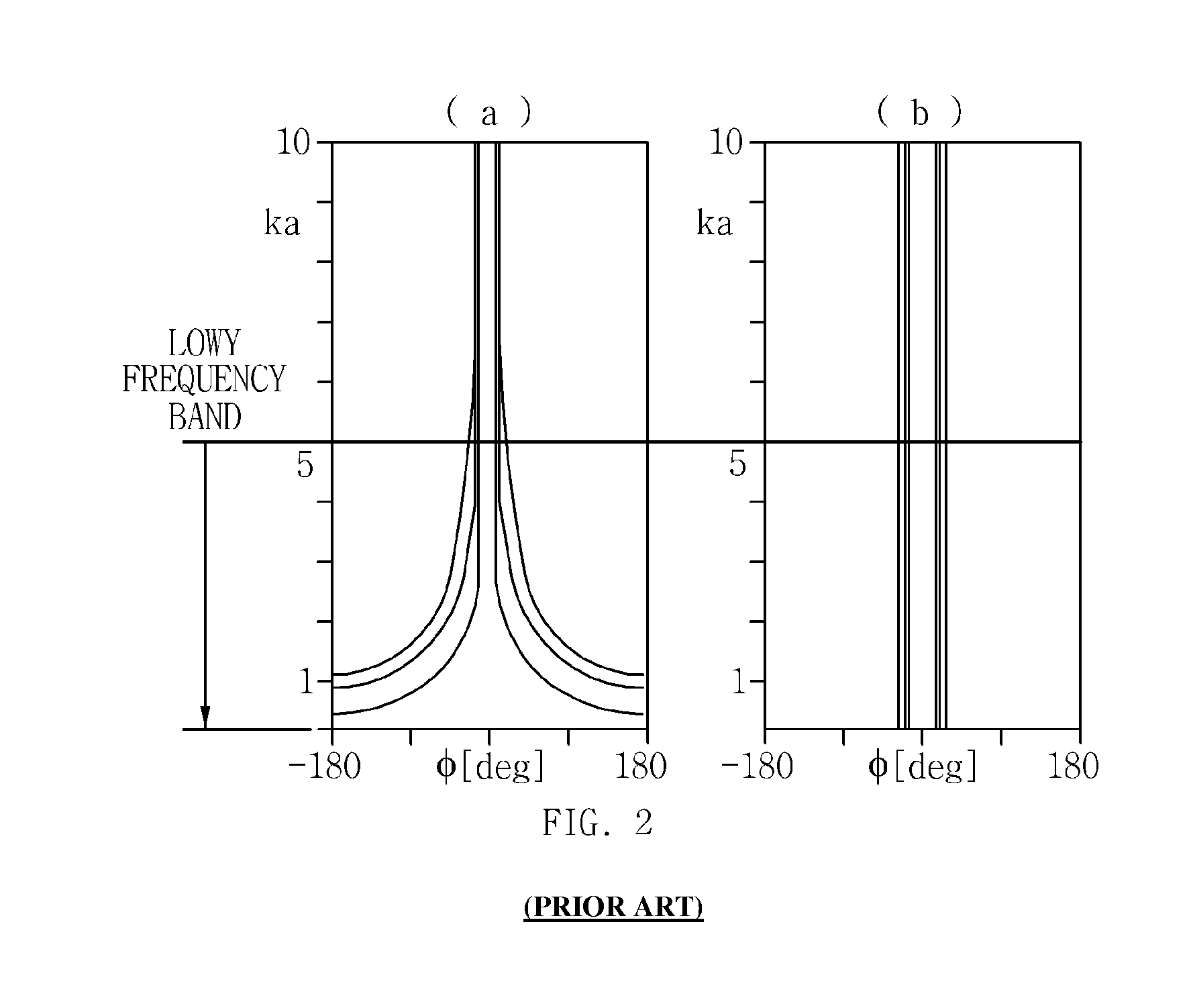
However, in the above delay-sum beam forming technique, there is a limitation in localization of a low frequency noise source (i.e., equal to or less than about 500 Hz) that has a sufficiently long wavelength compared to an interval between microphones adjacent to each other in the microphone array.
This limitation inevitably occurs in the delay-sum beam forming technique.
In the case of a low frequency noise source, when a typical beam forming method is used, the resolution is reduced due to a reduction of visualization performance, causing a limitation in the localization of the noise source.
However, in the above acoustic holography technique, only near field estimation is possible due to a limitation on the numerical formula.
Accordingly, a lot of numerical calculations are needed, and therefore analysis is delayed.

Method used


Image

  • Technique for localizing sound source
  • Technique for localizing sound source
  • Technique for localizing sound source

Examples


Embodiment Construction

[0037]Hereinafter reference will now be made in detail to various embodiments of the present invention, examples of which are illustrated in the accompanying drawings and described below. While the invention will be described in conjunction with exemplary embodiments, it will be understood that present description is not intended to limit the invention to those exemplary embodiments. On the contrary, the invention is intended to cover not only the exemplary embodiments, but also various alternatives, modifications, equivalents and other embodiments, which may be included within the spirit and scope of the invention as defined by the appended claims.

[0038]It is understood that the term “vehicle” or “vehicular” or other similar term as used herein is inclusive of motor vehicles in general such as passenger automobiles including sports utility vehicles (SUV), buses, trucks, various commercial vehicles, watercraft including a variety of boats and ships, aircraft, and the like, and inclu...


PUM


Abstract

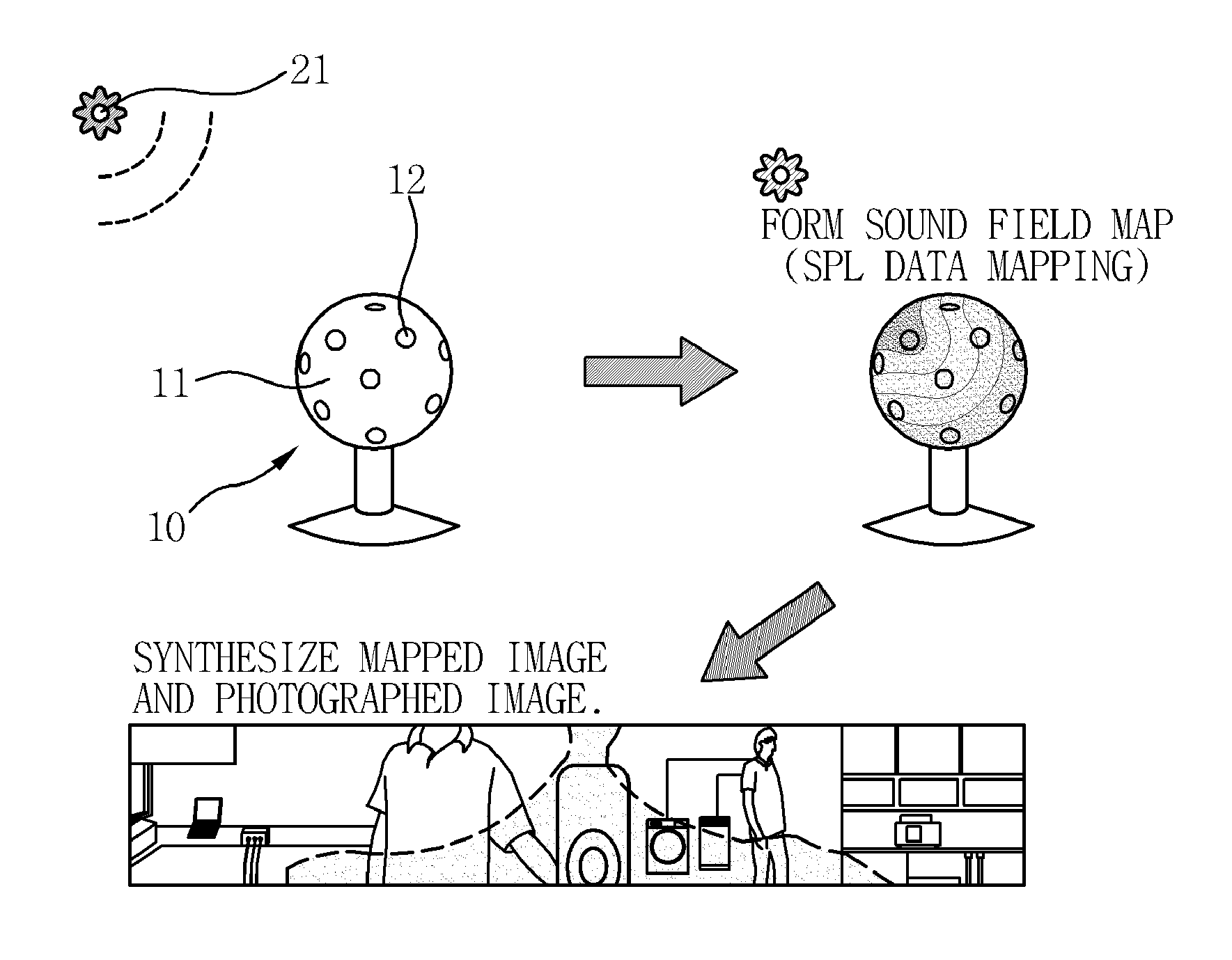
Disclosed is a technique for localizing a sound source. In the technique, a sound pressure signal measured by microphones is acquired using a spherical microphone array sensor where the microphones are fixedly arranged on a surface of a spherical body. A sound pressure distribution on the surface of the spherical body is obtained by a controller from a sound pressure calculation formula for calculating a sound pressure at a certain location of a spherical surface using the sound pressure signal measured by the microphones as an input value. A location of the sound source is estimated from the obtained sound pressure distribution.

Description

CROSS-REFERENCE TO RELATED APPLICATION[0001]This application claims under 35 U.S.C. §119(a) the benefit of Korean Patent Application No. 10-2011-0131710 filed Dec. 9, 2011, the entire contents of which are incorporated herein by reference.BACKGROUND[0002](a) Technical Field[0003]The present invention relates to a technique for localizing a sound source. More particularly, it relates to a technique for localizing a sound source, which can estimate sound pressure distribution with respect to a low frequency noise source, and can improve the resolution of sound field visualization with respect to the low frequency noise source.[0004](b) Background Art[0005]As the noise characteristics of various products such as vehicles and home appliances are recognized as an important performance indicator, efforts to manufacture products producing less noise have been made at the development stage. A method of finding the location and the cause of noise generation and reducing noise through design ...

Claims


Application Information

Patent Timeline
Patent Type & Authority Patents(United States)
IPC IPC(8): H04R3/00G01S3/808H04R1/40H04R29/00
CPCG01S3/808H04R3/005H04R1/406H04R29/008H04R2201/401H04R2430/20H04R2499/13G01S3/80G01H15/00
Inventor LEE, JONG HYUNLEE, MYUNG HANCHO, MUN HWANIH, KANG DUCK
Owner HYUNDAI MOTOR CO LTD
Learn More