Wireless and visual hybrid motion capture system

a motion capture and hybrid technology, applied in the field of portable wireless mobile device computer systems, can solve the problems of inaccurate and inconsistent subjective analysis based on video, inability to be used outside of the environment, and various limitations of the techniqu

Active Publication Date: 2016-04-26
NEWLIGHT CAPITAL LLC
View PDF306 Cites 28 Cited by
  • Summary
  • Abstract
  • Description
  • Claims
  • Application Information

AI Technical Summary

Benefits of technology

[0013]Embodiments of the invention enable a wireless and visual hybrid motion capture system. The apparatus allows for the measurement of orientation (North / South, and / or two horizontal axes and the vertical axis) and acceleration using an inertial measurement unit, or accelerometers and / or magnetometers, and / or gyroscopes. The apparatus may also include identifiers that enable a specific apparatus to be identified. The identifiers may be a serial number for example. Utilizing this apparatus enables the identification of a specific golfer, specific club and also enables perform motion capture and / or display with a system that includes a television and / or mobile device having a visual display and an optional camera and capable of obtaining data from at least one motion capture element such as a visual marker and / or a wireless sensor. The system can also integrate with standalone cameras, or cameras on multiple mobile devices. The system also enables the user to analyze and display the motion capture data in a variety of ways that provide immediate and easy to understand graphical information associated with the motion capture data. The apparatus enables the system to also determine how “centered” an impact is with respect to a ball and a piece of equipment, such as a golf club for example. The system also allows for fitting of equipment including shoes, clubs, etc., and immediate purchasing of the equipment even if the equipment requires a custom assemble-to-order request from a vendor.
[0018]In one or more embodiments of the invention, a sensor may be utilized that includes a passive marker or active marker on an outside surface of the sensor, so that the sensor may also be utilized for visual tracking (either two-dimensional or three-dimensional) and for orientation, position, velocity, acceleration or any other physical quantity produced by the sensor. Visual marker embodiments of the motion capture element(s) may be passive or active, meaning that they may either have a visual portion that is visually trackable or may include a light emitting element such as a light emitting diode (LED) that allows for image tracking in low light conditions. This for example may be implemented with a graphical symbol or colored marker at the end of the shaft near the handle or at the opposing end of the golf club at the head of the club.
[0019]The sensors utilized with embodiments of the apparatus may be generally mounted on or near opposing ends of a golf club and may integrate with other sensors coupled to equipment, such as shoes, pants, shirts, gloves, clubs, bats, racquets, balls, etc., and / or may be attached to a user in any possible manner. For example, one or more embodiments of the sensor can fit into a weight port of a golf club, and / or in the handle end of the golf club. Other embodiments may fit into the handle of, or end of, a tennis racquet or baseball bat for example. One or more embodiments of the invention may also operate with balls that have integrated sensors as well. Alternatively, the system may calculate the virtual flight path of a ball that has come in contact with equipment moved by a player. For example with a golf club having a sensor integrated into a weight port of other portion of the end of the club striking the golf ball and having a second sensor located in the tip of the handle of the golf club, or in one or more gloves worn by the player, an angle of impact can be calculated for the club. By knowing the loft of the face of the club, an angle of flight may be calculated for the golf ball. In addition, by sampling the sensor at the end of the club at a high enough speed to determine oscillations indicative of where on the face of the club the golf ball was struck, a quality of impact may be determined. These types of measurements and the analysis thereof help an athlete improve, and for fitting purposes, allow an athlete to immediately purchase equipment that fits correctly.

Problems solved by technology

This technique has various limitations including inaccurate and inconsistent subjective analysis based on video for example.
Known implementations utilize a stationary multi-camera system that is not portable and thus cannot be utilized outside of the environment where the system is installed, for example during an athletic event such as a golf tournament.
These fixed installations are extremely expensive as well.
There are no known systems that utilize as little as one visual marker or sensor and a mobile device to analyze and display motion capture data associated with a user and / or piece of equipment.
There are no known systems that allow for a group of mobile devices to share data to form three-dimensional motion capture data by triangulation of visual markers.
There are no known systems that allow for a mobile device without a camera to obtain images from cameras or other mobile devices with cameras to display motion capture data.
There are no known mobile motion captures systems that allow for a user to align a camera correctly along the horizontal before capture of motion data having horizontally aligned images.
There are no known systems that allow for motion capture elements such as wireless sensors to seamlessly integrate or otherwise couple with a golf club, for example in the weight port of a golf club or at the end shaft near the handle so as to provide a wireless golf club, configured to capture motion data.
In addition, there are no known systems that allow for motion capture elements such as wireless sensors to seamlessly integrate or couple with shoes, gloves, shirts, pants, belts, or other equipment, or a user, in such a small format that the user is not aware that the sensors are located in these items.
In addition, for sports that utilize a piece of equipment and a ball, there are no known portable wireless mobile device motion capture and analysis systems that allow the user to obtain immediate visual feedback regarding ball flight distance, swing speed, swing efficiency of the piece of equipment or how centered an impact of the ball is, i.e., where on piece of equipment the collision of the ball has taken place.
In addition, there are no known systems that provide portable wireless mobile device motion capture and analysis for equipment fitting and subsequent point-of-sale decision making for instantaneous purchasing of equipment that fits an athlete.
Furthermore, no known systems allow for custom order fulfillment such as assemble-to-order (ATO) for custom order fulfillment of sporting equipment, for example equipment that is built to customer specifications based on portable wireless mobile device motion capture and analysis, and shipped to the customer to complete the point of sales process.

Method used


Image

  • Wireless and visual hybrid motion capture system
  • Wireless and visual hybrid motion capture system
  • Wireless and visual hybrid motion capture system

Examples


Embodiment Construction

[0066]A wireless and visual hybrid motion capture system will now be described. In the following exemplary description numerous specific details are set forth in order to provide a more thorough understanding of the ideas described throughout this specification. It will be apparent, however, to an artisan of ordinary skill that embodiments of ideas described herein may be practiced without incorporating all aspects of the specific details described herein. In other instances, specific aspects well known to those of ordinary skill in the art have not been described in detail so as not to obscure the disclosure. Readers should note that although examples of the innovative concepts are set forth throughout this disclosure, the claims, and the full scope of any equivalents, are what define the invention.

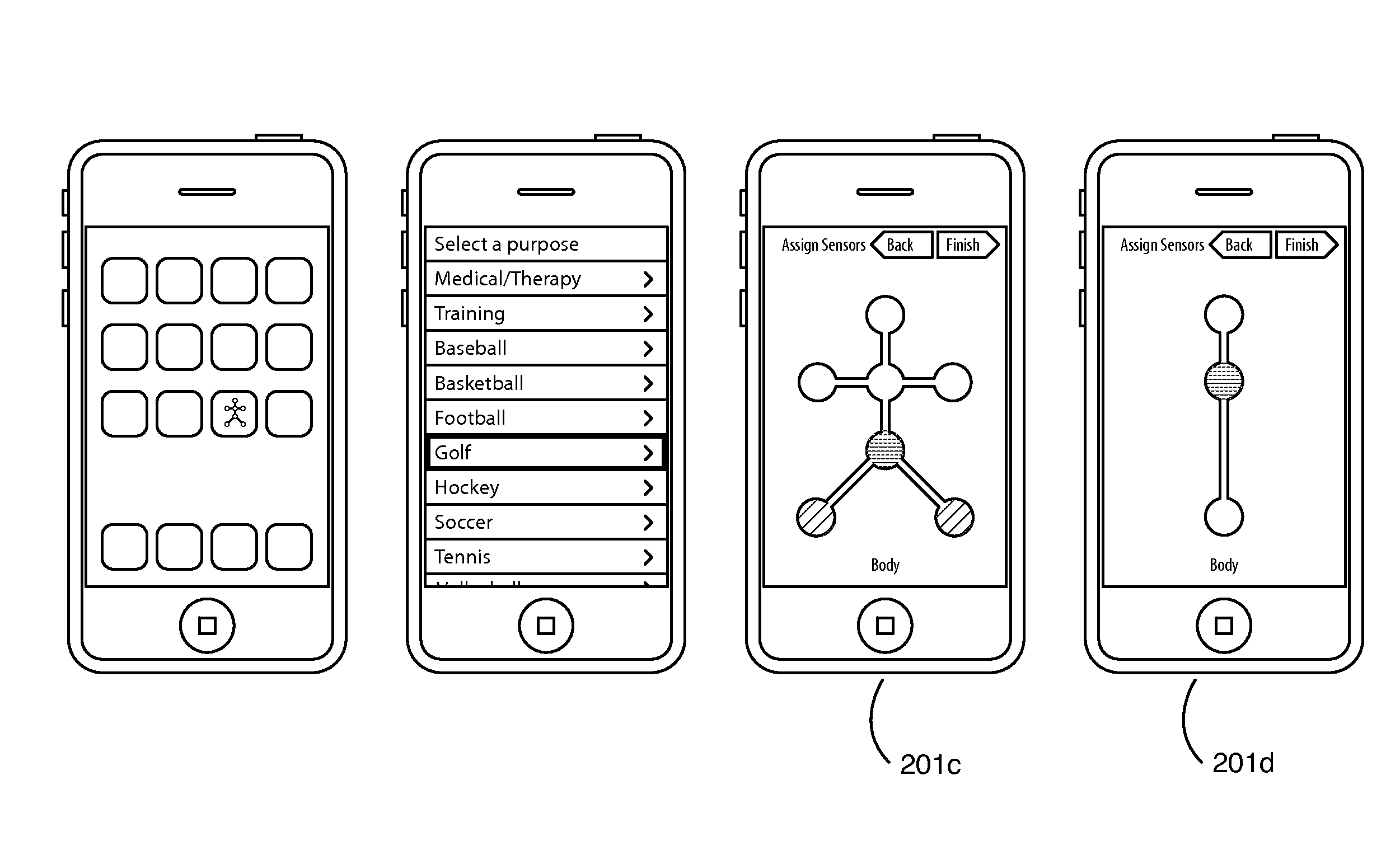
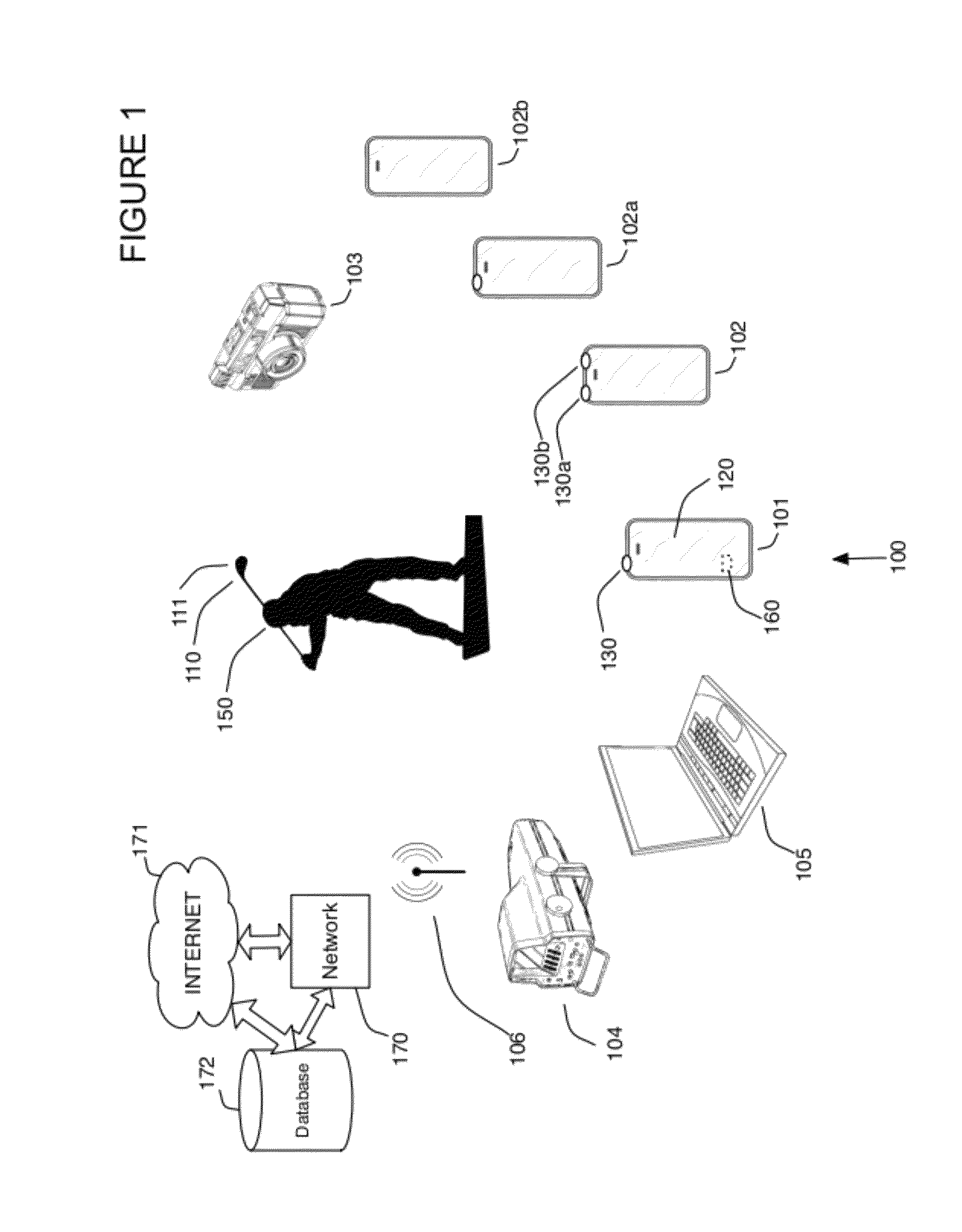
[0067]FIG. 1 illustrates an embodiment of a system that may utilize motion capture elements as shown in FIGS. 11, 12, 38, 39, 40 and 41 for example that enables a portable wireless mobil...


PUM


Abstract

The system includes motion capture elements such as visual markers and sensors utilized in the capture of motion data both wirelessly and visually. The system may send a unique identifier and spatial data over a self-contained radio and antenna wirelessly to an external system that may analyze and display the spatial data in a user-friendly manner.

Description

[0001]This application is a continuation-in-part of U.S. Utility patent application Ser. No. 12 / 868,882 filed 26 Aug. 2010 now U.S. Pat. No. 8,994,826, the specification of which is hereby incorporated herein by reference.BACKGROUND OF THE INVENTION[0002]1. Field of the Invention[0003]One or more embodiments setting forth the ideas described throughout this disclosure pertain to the field of portable wireless mobile device computer systems, motion capture elements such as visual markers and sensors utilized in the capture of motion data. More particularly, but not by way of limitation, one or more aspects of the disclosure enable a wireless and visual hybrid motion capture system.[0004]2. Description of the Related Art[0005]One known technique to teach effective body mechanics utilizes video recording of an athlete and analysis of the recorded video of an athlete. This technique has various limitations including inaccurate and inconsistent subjective analysis based on video for exam...

Claims


Application Information

Patent Timeline
Patent Type & Authority Patents(United States)
IPC IPC(8): A63B69/36A63B24/00G01D21/00A63B71/06H04M1/725H04W28/04H04W84/18G06K9/00H04M1/72412
CPCA63B69/3623A63B24/0006A63B24/0021A63B69/3614A63B69/3632A63B71/0622G01D21/00A63B2024/0031A63B2071/0647A63B2102/02A63B2102/18A63B2102/32A63B2220/10A63B2220/12A63B2220/30A63B2220/40A63B2220/805A63B2220/806A63B2220/807A63B2220/833A63B2220/836A63B2225/20A63B2225/50G06K9/00342H04M1/7253H04M2250/52H04W28/048H04W84/18H04W28/04H04M1/72412A63B60/46G06V40/23A63B2102/22
Inventor BENTLEY, MICHAEL
Owner NEWLIGHT CAPITAL LLC
Why Eureka
Try Eureka