Mixing blade for cementitious material

a technology of cementitious materials and tools, which is applied in the direction of mixing, mixing, chemistry apparatus and processes, etc., can solve the problems of not working well to thoroughly mix dry cementitious materials, not having the same area as a conventional hoe, and not being able to achieve satisfactory mixing of concrete and other dry cementitious materials with water. achieve the effect of more thorough, uniform and efficient mixing

Active Publication Date: 2016-04-26
ROYE SAMUEL L
View PDF13 Cites 0 Cited by
  • Summary
  • Abstract
  • Description
  • Claims
  • Application Information

AI Technical Summary

Benefits of technology

[0007]The invention provides improved mixing blades for cementitious material for use with hand tools, and improved fluid injecting tools using such blades for mixing cementitious materials that address the foregoing and other known problems of available mixing tools. Blades and tools employing the improved blades in accordance with the invention allow for more thorough, uniform and efficient mixing of cementitious materials.

Problems solved by technology

However, the blade does not have the same area as a conventional hoe and it does not work well to mix thoroughly the dry cementitious materials, particularly concrete, and water to form the desired slurry.
While the V-shaped blade performs somewhat better than the triangularly-shaped solid blade, it also does not perform satisfactorily in mixing concrete and other dry cementitious materials with water.
Bagged concrete contains gravel, typically ⅜ inch pea gravel, which makes it more difficult than other types of cementitious materials to mix thoroughly into a uniform, consistent slurry.
However, their rounded tips do not allow the blades to scrape effectively the bottom of the mixing container.

Method used


Image

  • Mixing blade for cementitious material
  • Mixing blade for cementitious material
  • Mixing blade for cementitious material

Examples


first embodiment

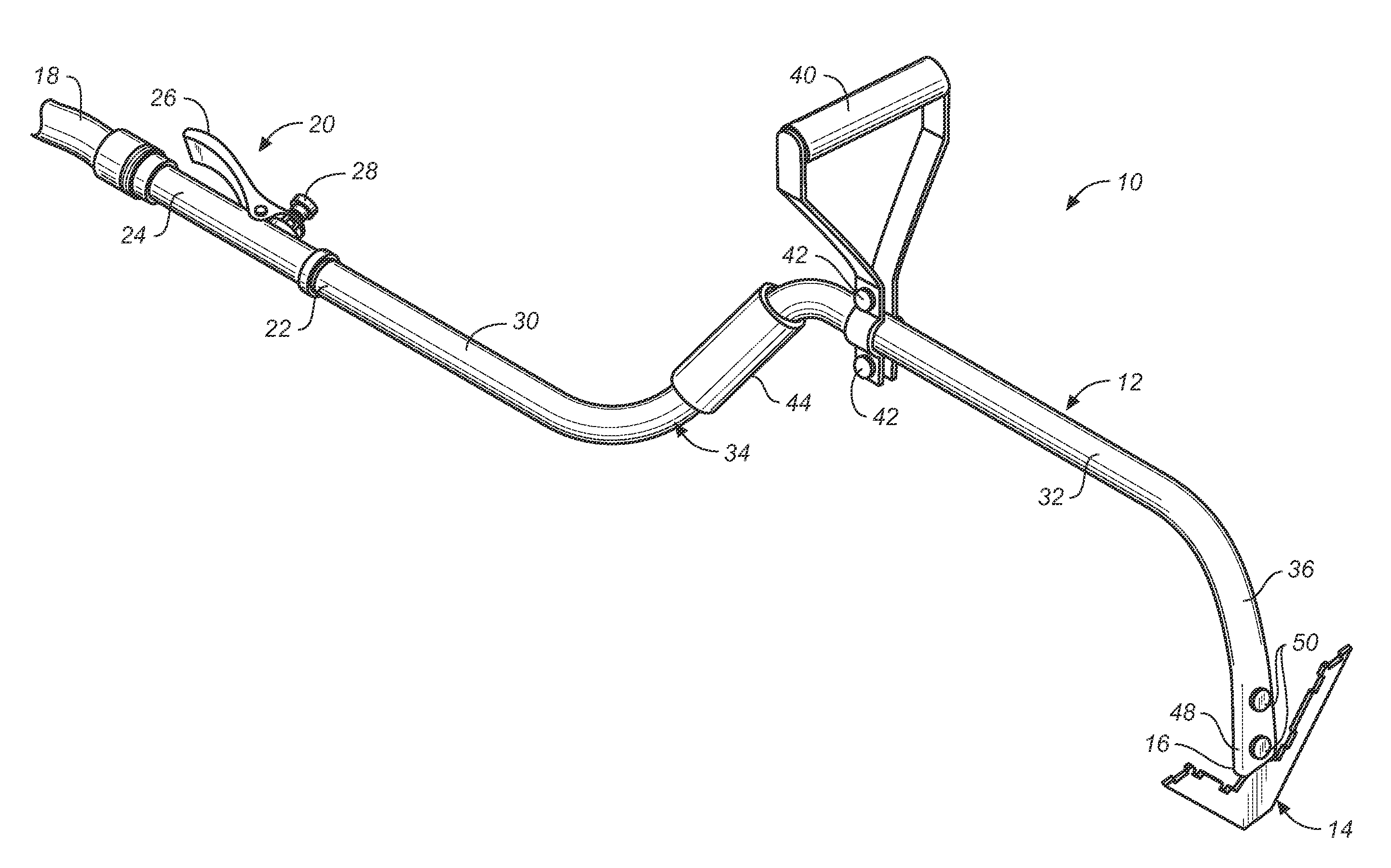
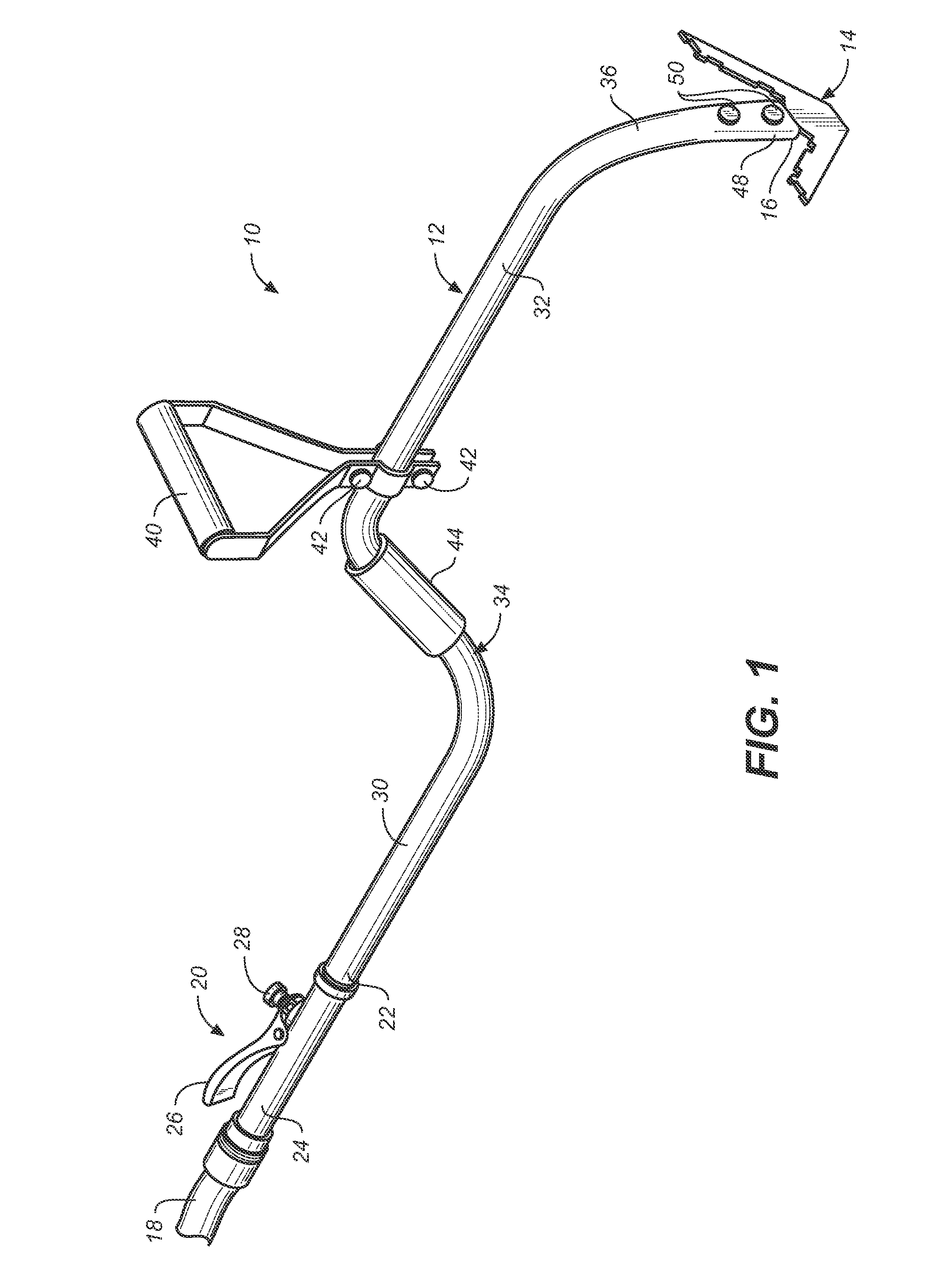
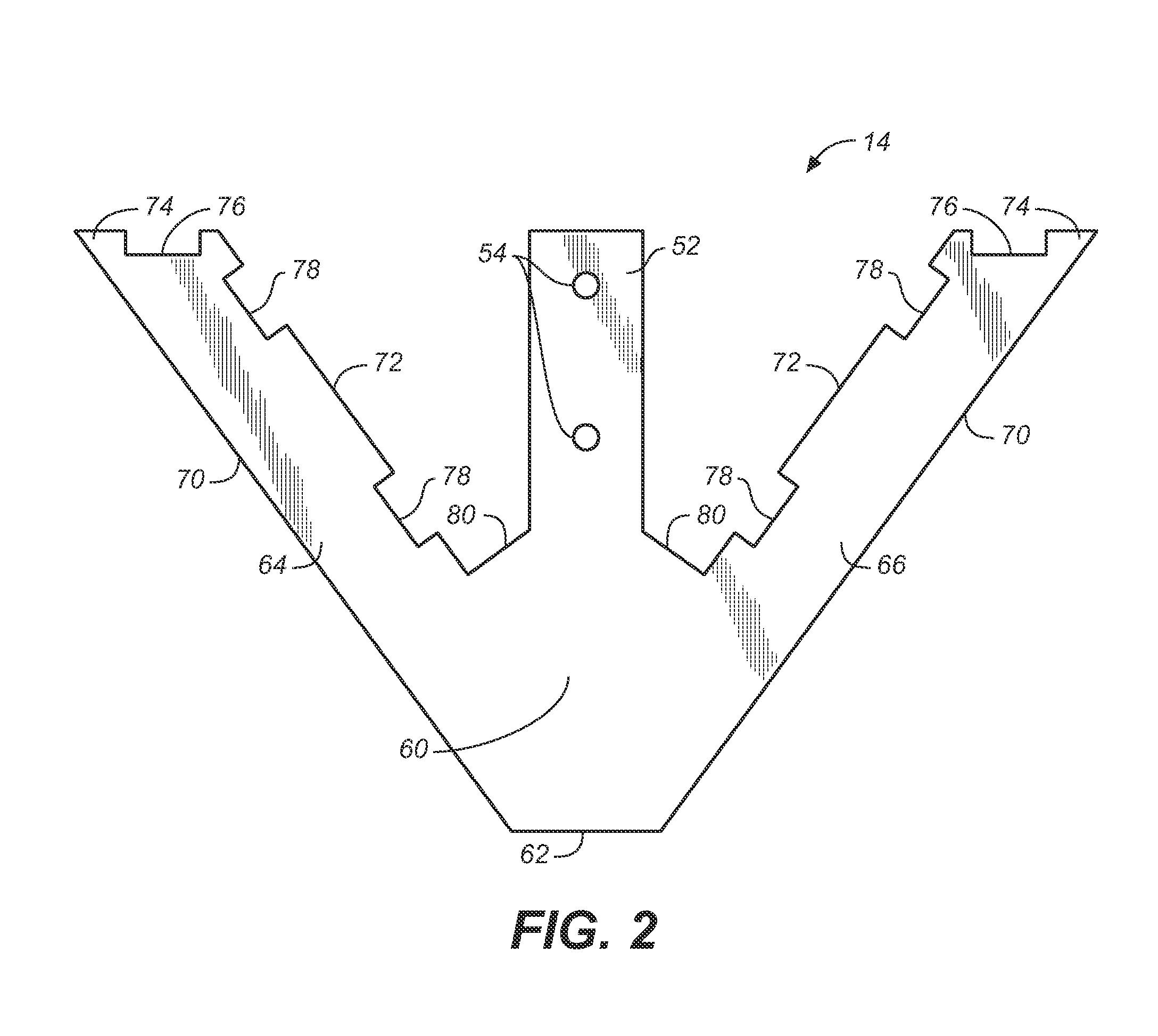
[0019]FIGS. 1-4 illustrate a mixing blade 14 in accordance with the invention. As shown best in FIGS. 2, 3 and 4, blade 14 is rigid V-shaped planar member having a central bottom blade section 60 from which tang 52 extends, a straight bottom edge 62, and a pair of legs 64, 66, respectively, extending outwardly and upwardly at inclined angles from the central blade section 60 and the bottom edge 62 of the blade to impart a V-shape to the blade. Tang 52 may bisect the legs and extend upwardly from the central section of the member about a central axis of the blade for connection to the handle of tool 10. Each of the legs 64, 66 of the blade may have an outer lateral edge 70 extending upwardly from bottom edge 62, an interior lateral edge 72 parallel to the outer lateral edge 70, and a top edge 74 that extends between the outer and interior lateral edges of each leg, is generally parallel to bottom edge 62, and is normal to the tang 52 and the central axis of the blade. The interior la...

second embodiment

[0023]FIG. 5 illustrates a blade 100 in accordance with the invention that may be used with tool 10. As shown, blade 100 comprises a triangularly shaped blade member having lateral side edges 102, 104 which slope upwardly from a straight bottom edge 106, a top edge 108 and a central triangularly shaped cut-out or opening 110 through the blade that preferably matches the triangular shape of the blade. The straight bottom edge truncates the triangular shape of the blade at the tip region. Opening 110 may be sized to form a pair of side legs 112, 114 that are generally similar in size and shape to legs 64 and 66 of V-shaped blade 14, and that are upwardly inclined at an angle from a bottom portion 116 of the blade 100. A top member 118 may extend between upper ends of the legs 112 and 114. The top member 118 may be formed with one or more notches or cut-outs 120 in its top edge 108. The blade 100 thus has a generally triangular open frame shape. The cut-outs may be similar to the cut-o...

third embodiment

[0026]FIG. 6 illustrates a multi-purpose mixing blade 200 in accordance with the invention that may be used with tool 10. Blade 200 may be substantially the same as blade 100 of FIG. 5, comprising a triangularly-shaped blade having a triangularly-shaped central opening 202, except that blade 200 has cut-outs 204 formed in the interior edges 206 of lateral side legs 208 and 210 within the central triangularly-shaped opening 202. As with blade 100, blade 200 may have cut-outs 216 formed in a top edge 220 of the blade.

[0027]Blade 200 functions in a similar way to that described for blades 14 and 100. Cut-outs 204 and 216 function as previously described to provide edges for spinning gravel in concrete mix, and the central opening 202 in the blade is effective for mixing other types of materials such as mortar and grout, as described above for blade 100.

[0028]Blades 100 and 200 of FIGS. 5 and 6, respectively, may be formed in a similar manner to that described for blade 14, preferably b...


PUM


Abstract

A tool for infecting fluid into and mixing with cementitious material includes a V-shaped or triangularly shaped blade connected to a tubular handle, the blade having a central open area, a top edge and interior edges. The top and interior edges have a plurality of notched cut-outs that together with the edges of the blade form corners for engaging and mixing the cementitious material and fluid as the blade moves through it.

Description

BACKGROUND[0001]This invention relates generally to tools for mixing cementitious materials, and further to improved mixing blades for hand tools such as hoes and the like for mixing water or other fluids with dry cementitious materials to form slurries.[0002]Cementitious materials such as concrete, mortar, tile grout, plaster and the like typically comes in bags as a “dry mix”. In order to be used, the dry mix material must be mixed with water or other fluids to form a slurry having an appropriate consistency. Generally, this is done by gradually adding water to the dry mix material and stirring or the water and the material using a hand tool such as a hoe, a trowel, or the like to completely and thoroughly mix the material and the water to form a uniform slurry of the desired consistency.[0003]U.S. Pat. No. 5,947,039 to Lundgren et. al discloses a hand-held water injecting tool for gradually adding water to and mixing dry cementitious materials such as concrete. The Lundgren tool ...

Claims


Application Information

Patent Timeline
Patent Type & Authority Patents(United States)
IPC IPC(8): B01F13/00B25G1/10B25G3/26
CPCB25G1/102B25G3/26B01F13/002B01F33/5011
Inventor ROYE, SAMUEL L.
Owner ROYE SAMUEL L
Why Eureka
Try Eureka