Valve arrangement of a commercial cooking device and commercial cooking device

a cooking device and valve arrangement technology, applied in the direction of baking, household heating details, heating types, etc., can solve the problem of unfavorable effect of sucking waste water into the cooking chamber, and achieve the effects of reducing flow resistance, improving pressure control characteristics, and accelerating releas

Active Publication Date: 2016-05-03
WELBILT DEUT GMBH
View PDF5 Cites 1 Cited by
  • Summary
  • Abstract
  • Description
  • Claims
  • Application Information

AI Technical Summary

Benefits of technology

[0008]The present disclosure provides a valve arrangement that is able to reduce the flow resistance so that its pressure control characteristics are improved. In particular, the present disclosure overcomes the shortcomings of the state of the art. The present disclosure provides for faster release of any high pressure or over pressure in the cooking chamber, and also provides for faster balancing of pressures between the atmosphere and the cooking chamber when the cooking chamber is in a low pressure or vacuum state. In addition, the present disclosure provides for automatic balancing of such a low pressure or vacuum situation in the cooking chamber.
[0009]The valve arrangement according to the present disclosure makes it possible to use a larger valve disc that, in conjunction with the enlarged discharge cross-section of the valve seat opening, results in the advantage of a lower flow resistance. This, in turn, enhances the dehumidification of the cooking chamber and improves the balance of any pressure differences between the cooking chamber and the atmosphere.
[0010]In one particularly preferred embodiment of the present disclosure, the valve disc means of the valve arrangement comprises a vacuum valve disc as well as a pressure relief valve disc. This results in the advantage of an integration of a high-pressure and a low-pressure function that makes it possible to balance both an increased pressure as well as a vacuum or reduced pressure within the cooking chamber. This embodiment is especially advantageous because the creation of a reduced pressure within the cooking chamber by, e.g., spraying cold water into the cooking chamber for drying the chamber atmosphere, can result in the undesirable effect of sucking waste water into the cooking chamber.

Problems solved by technology

This embodiment is especially advantageous because the creation of a reduced pressure within the cooking chamber by, e.g., spraying cold water into the cooking chamber for drying the chamber atmosphere, can result in the undesirable effect of sucking waste water into the cooking chamber.

Method used


Image

  • Valve arrangement of a commercial cooking device and commercial cooking device
  • Valve arrangement of a commercial cooking device and commercial cooking device
  • Valve arrangement of a commercial cooking device and commercial cooking device

Examples


Embodiment Construction

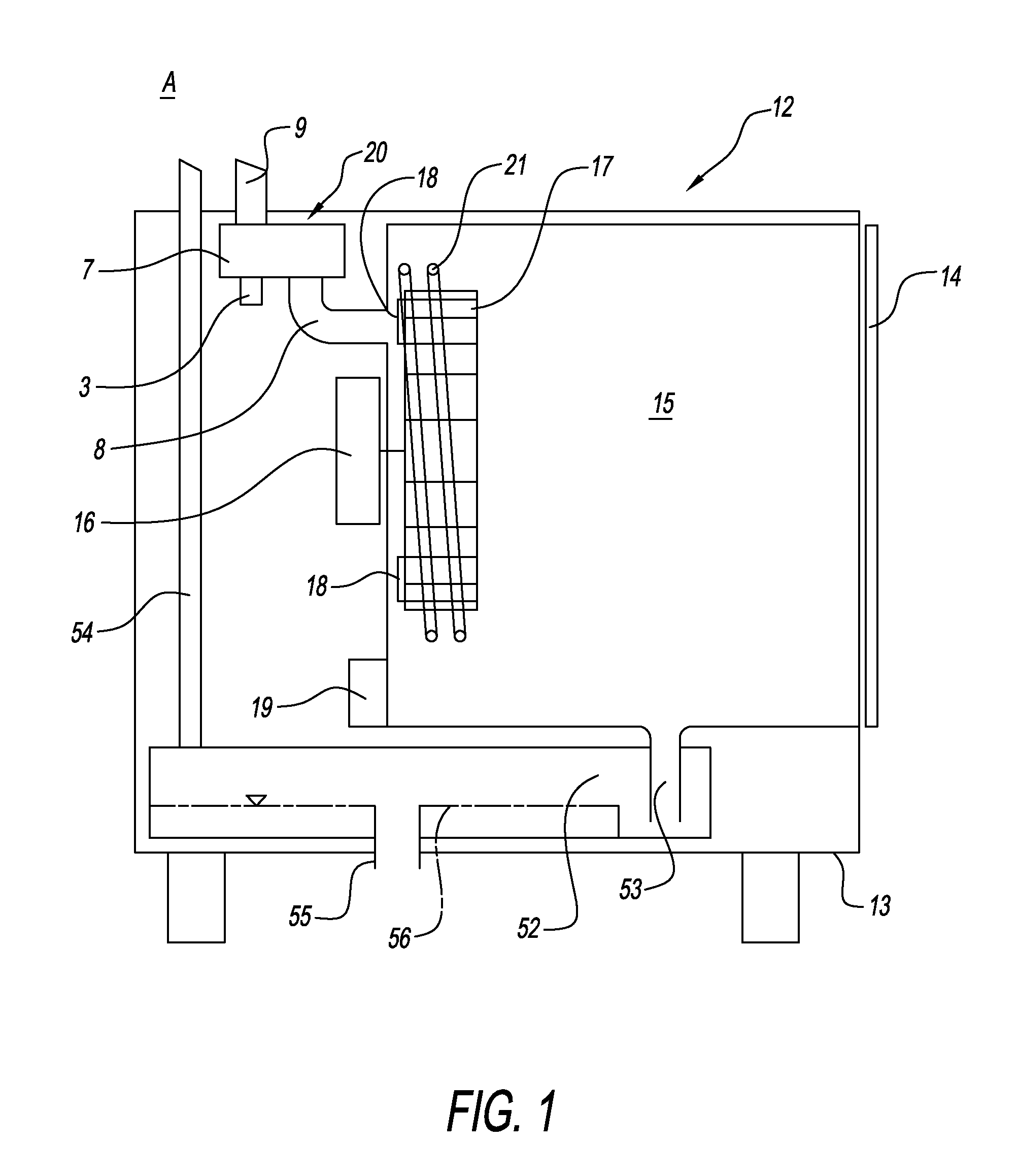
[0017]FIG. 1 shows commercial cooking device 12, in particular a combi-steamer. Cooking device 12 comprises housing 13 with door 14 that can be opened and closed to expose interior of cooking device 12, i.e., cooking chamber 15, in order to load and unload food products into and out of cooking chamber 15. Fan wheel 17 is located within cooking chamber 15. Fan wheel 17 is driven by motor 16 and comprises fan blades 18 at rear side of fan wheel 17 in order to create a slight negative pressure behind fan wheel 17. Finally, cooking device 12 comprises control means 19 that is adapted to control all the components of cooking device 12, and valve arrangement 20. Valve arrangement 20 is connected to cooking chamber 15 by means of first conduit 8 and to atmosphere A by means of second conduit 9. Cooking chamber heater 21 is disposed next to fan wheel 17. Condenser 52 is connected with cooking chamber 15 via outlet 53. Condenser has water level 56 and drain 55 as well as air vent 54 leading ...


PUM


Abstract

A valve structure includes a housing having an interior chamber, a first conduit connecting the interior chamber with a cooking chamber of a cooking device and having a first discharge cross-section, a second conduit connecting the interior chamber with the outside environment and having a second discharge cross-section, and at least one valve seat within the interior chamber having at least one valve seat opening which cooperates with at least one valve disc. The at least one valve disc moves between a closed position on the valve seat opening, and an open position spaced apart from the valve seat opening by changes in pressure in the cooking chamber. The valve operates to allow bidirectional flow of fluid to relieve over pressure and underpressure conditions, and enables automatic balancing of low pressure or vacuum in the cooking chamber.

Description

CROSS-REFERENCED APPLICATION[0001]This application claims priority to U.S. Provisional Application No. 61 / 591,701, filed on Jan. 27, 2012, which is incorporated herein in its entirety by reference thereto.BACKGROUND[0002]1. Field of the Disclosure[0003]The present disclosure relates to a valve arrangement of a commercial cooking device.[0004]2. Discussion of the Background Art[0005]A commercial cooking device comprises a cooking chamber enclosed by a door that can be opened and closed for providing access to the cooking chamber. If the door is opened during a cooking process, e.g., for loading or unloading food products, a pressure rise can occur when the door is closed as cold air streams into the cooking chamber and heats up and expands very quickly.[0006]In order to balance such a pressure rise, a known valve arrangement comprises a housing that is connected to the cooking chamber via a first conduit. The interior of the housing of the valve arrangement is also connected to the a...

Claims


Application Information

Patent Timeline
Patent Type & Authority Patents(United States)
IPC IPC(8): A21B3/13F24C15/20A47J27/00F16K31/12F24C15/32F16K31/06F16K17/04
CPCA47J27/00F24C15/2007F24C15/327F16K17/048F16K31/0655F16K17/196Y10T137/7904
Inventor RIEFENSTEIN, LUTZWURDINGER, GUENTER
Owner WELBILT DEUT GMBH
Why Eureka
Try Eureka