Turbine apparatus and methods

a technology of turbines and cylinders, applied in the field of turbines, can solve the problems of few successful practical applications of these machines, and achieve the effects of efficient intercepting off-axis or angular fluid flow, useful energy, and conversion of such angular fluid flow

Active Publication Date: 2016-05-03
BEASTON STEVEN D
View PDF73 Cites 10 Cited by
  • Summary
  • Abstract
  • Description
  • Claims
  • Application Information

AI Technical Summary

Benefits of technology

[0009]In certain example embodiments, turbines with helical blades oriented to efficiently intercept off axis or angular fluid flow, such as presented by whirlpool water flow patterns, are provided.
[0010]In certain preferred embodiments, turbines are provided having helical blades with major blade surfaces oriented to take advantage of whirlpool or circular-angle flow patterns, depending on geographic location of installation in the northern or southern hemisphere. In these or other example embodiments described herein, the pitch of the rotor and / or helical blade surfaces is variable based on water (or other fluid) flow or power generation needs. In such or other embodiments, one or more of the example turbines disclosed herein may be installed in a power generation system having a fluid flow path or pattern which includes, at least part of the time, circular or off axis angles of fluid flow. In such embodiments, certain example turbines are configured so that their helical vane blades have major blade surfaces oriented at angles to efficiently intercept off axis or angular fluid flow. That is, in certain example embodiments, the major blade surfaces are oriented, depending on their location of installation in the northern or southern hemisphere, so that their major blade surfaces are poised to better intercept clockwise or counter-clockwise whirlpool flow patterns, and then convert such angular fluid flow to useful energy more efficiently than prior art turbines.
[0012]In some example embodiments in which variable blade pitches are provided in the turbines, the helical vane blades are connected to the rotor blades via pivot connections (e.g., to prevent physical strain from harming or stressing the blades or turbine). In other example embodiments utilizing variable blade pitches, the helical vane blades are connected to the rotor blades via flexure or flexible connections. Of course, combinations of hinged and flexible or flexure connections may also be used between the helical and rotor blade portions. In still other example embodiments, and also useful to prevent strain in the turbine system or blades, the helical vane blades are connected to the shaft portion of the turbine rotor by a slideable joint, such as a male / female spline joint. By employing a slideable connection, when the pitch of the rotor and / or helical vane blades is adjusted, the slideable joint permits the connection point to travel up or down axis to accommodate or prevent physical stresses from being introduced into the blades (and / or retained within the blades) as a result of corresponding blade lengthening or shortening, while still providing for the efficient transmission of power or force to the rotor shaft. In such embodiments, or in alternative embodiments, a slideable joint or connection may also be employed between the rotor blades and the rotor shaft. Pivot connections, such as between the rotor shaft and the helical blades, may additionally be employed (e.g., such as using a shoulder bolt). Of course, when utilizing such joints or connections, low friction materials and / or lubricants may be employed (though not required) to facilitate proper or smooth operation by reducing friction among moving parts.
[0013]In still further example embodiments, a conical or beveled lip may be used to improve or promote smooth fluid flow over turbine parts, such as over the male / female spline joint connection of the helical vane blade to the rotor shaft. In other example embodiments, a cone is utilized on the downstream end of the shaft to minimize turbulence.

Problems solved by technology

In this regard, although various hydropower machines have been developed and / or proposed in recent times, few of these machines have been successful in practical application, a notable exception being a conventional turbine.

Method used


Image

  • Turbine apparatus and methods
  • Turbine apparatus and methods
  • Turbine apparatus and methods

Examples


Embodiment Construction

[0021]For a more complete understanding of the present invention and advantages thereof, reference is now made to the following description of various illustrative and non-limiting embodiments thereof, taken in conjunction with the accompanying drawings in which like reference numbers indicate like features.

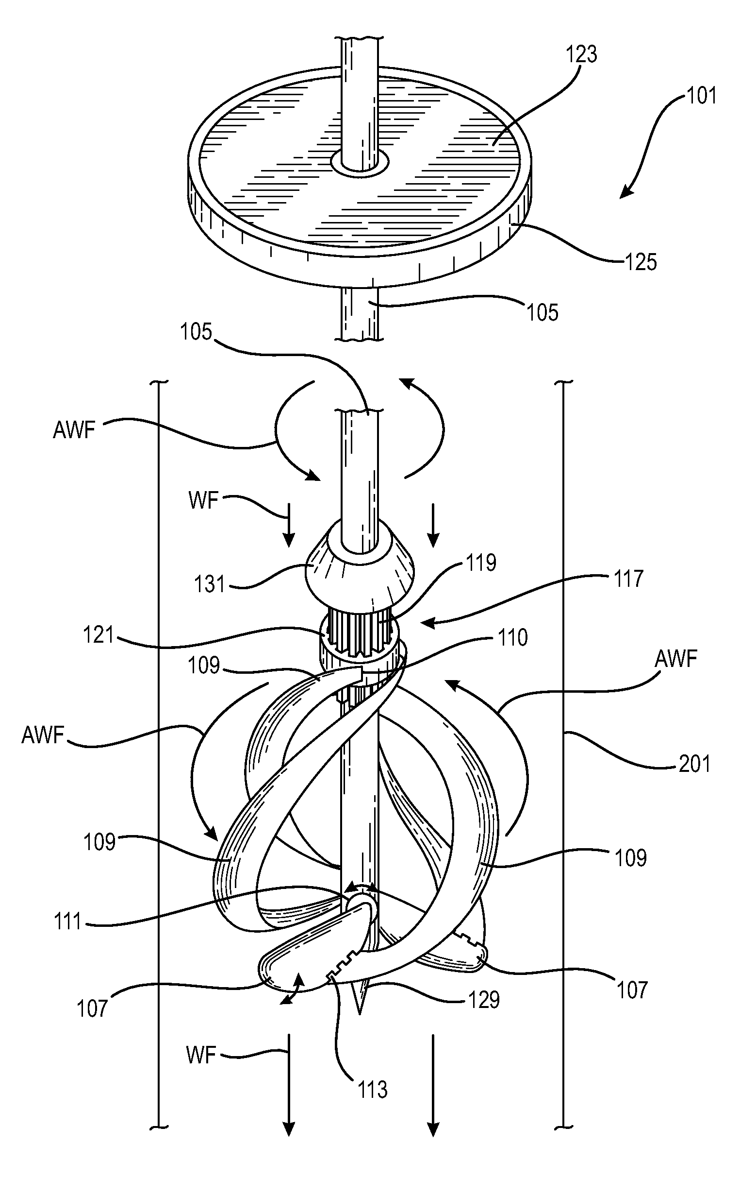
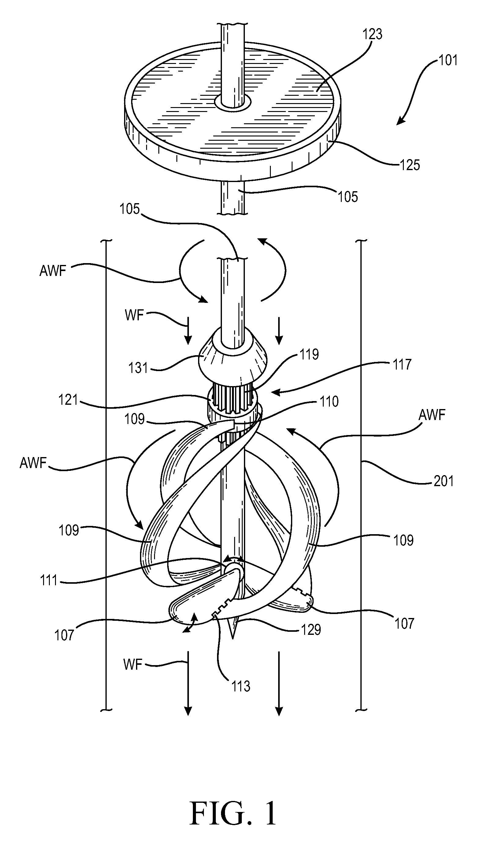
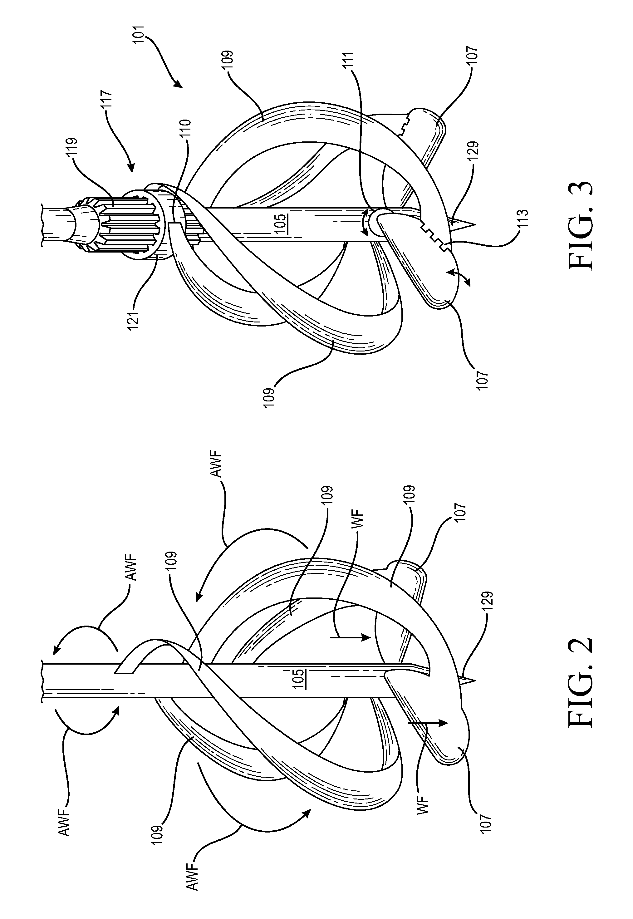
[0022]In the northern hemisphere of the earth, water draining through a narrowing conveyance or passageway, such as a pipe or conduit, forms an angular flow pattern or whirlpool traveling in a counter-clockwise direction. In the southern hemisphere, a similar angular flow pattern forms during draining, albeit in a clockwise direction. Since, in a hydro-power system, water drains from a reservoir into and through narrow piped conveyances such as penstocks and draft tubes, whirlpools or off axis or angular flow patterns form in these hydro-power system conveyances. The present invention, in order to take advantage of the natural tendency of water to form off axis or angular flow pa...


PUM


Abstract

Turbines and methods for their use, for generating power utilizing the flow of water or other fluids. In certain embodiments, turbines with helical blades oriented to efficiently intercept off axis or angular fluid flow, such as presented by whirlpool water flow patterns. In certain preferred embodiments, turbines having helical blades with major blade surfaces oriented to take advantage of whirlpool or circular-angle flow patterns, depending on geographic location of installation in the northern or southern hemisphere. In still other embodiments, turbines in which the pitch of rotor and / or helical blade surfaces is variable.

Description

RELATED APPLICATION DATA[0001]This application claims priority to U.S. Patent Application No. 61 / 624,081, filed Apr. 13, 2012, entitled APPARATUS AND METHOD FOR ENHANCED HYDRO-TURBINES, and invented by Steven D. Beaston, the entirety of which is hereby incorporated by reference. U.S. Pat. Nos. 6,933,624 and 6,831,373 are also each hereby incorporated in their entireties by reference.FIELD OF THE INVENTION[0002]This invention relates to turbines and methods for their use, for generating power utilizing the flow of water or other fluids. In certain embodiments, this invention relates to turbines with helical blades oriented to efficiently intercept off axis or angular fluid flow, such as presented by whirlpool water flow patterns. In certain preferred embodiments, this invention relates to turbines having helical blades with major blade surfaces oriented to take advantage of whirlpool or circular-angle flow patterns, depending on geographic location of installation in the northern or ...

Claims


Application Information

Patent Timeline
Patent Type & Authority Patents(United States)
IPC IPC(8): F03B3/14F03B3/12F03B13/14
CPCF03B3/14F03B13/14F05B2250/25Y02E10/38Y02E10/30
Inventor BEASTON, STEVEN D.
Owner BEASTON STEVEN D
Why Eureka
Try Eureka