Mechanized multi-instrument surgical system

a multi-instrument, surgical technology, applied in the field of access devices and ports, can solve the problems of prolonged patient recovery, increased complications, post-operative herniation, etc., and leave the patient with four abdominal scars

Active Publication Date: 2016-05-10
GREAT BELIEF INT LTD
View PDF72 Cites 735 Cited by
  • Summary
  • Abstract
  • Description
  • Claims
  • Application Information

AI Technical Summary

Problems solved by technology

While this procedure is very effective and has stood as the gold standard for minimally invasive surgery, it suffers from a number of drawbacks.
One such drawback is the need for multiple incisions to place the four ports, which increases the risk of complications such as post-operative herniation and prolonged patient recovery

Method used


Image

  • Mechanized multi-instrument surgical system
  • Mechanized multi-instrument surgical system
  • Mechanized multi-instrument surgical system

Examples


second embodiment

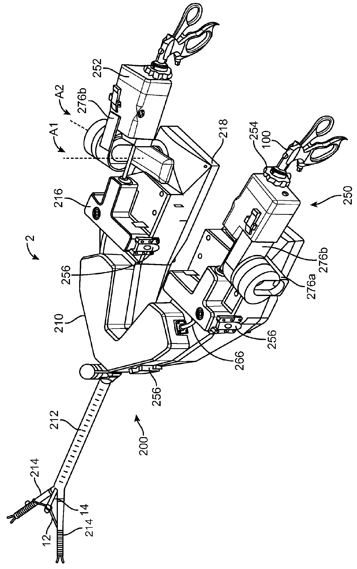
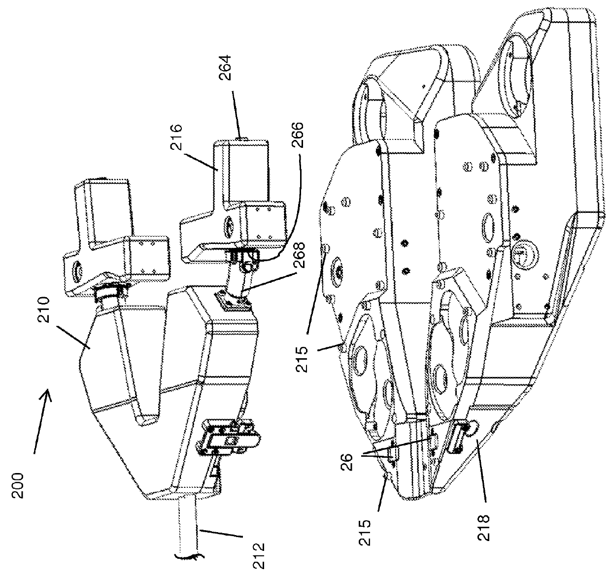
[0162]The system 2A of the second embodiment, shown in FIG. 19, differs from the first embodiment primarily in that the features of the roll driver are incorporated into the base. More particularly, a base 218a includes an elevated portion 216a that houses the roll drive tube 248 (not shown). An instrument passage extends between a proximal opening 264a and a distal opening (not shown) in the elevated portion 216a. The instrument shaft extends through the passage elevated portion 216a between the command interface 250 and the finger drive assembly 200. A sterile tubular insert (not shown) is insertable through the instrument passage in the elevated portion 216a to prevent the instrument 100 from contaminating the passage.

third embodiment

[0163]Referring to FIG. 20, a third embodiment of a surgical access system 2B includes a body 210a and an insertion cannula 212 extending distally from the body 210a. Fingers 214 extend from the insertion cannula 212. The finger 214 may have properties similar to those described elsewhere in this application.

[0164]Each finger includes a dedicated deployment mechanism operable to independently reposition the distal portion of the fingers 214 to increase or decrease its lateral separation from the longitudinal axis of the insertion cannula 212. Each deployment mechanism includes a rigid, longitudinally slidable, member 14a and at least one link arm 12a (two are shown for each finger). The rigid member 14a may be constructed of a proximal portion comprising a straight, single-lumen, tube made of stainless steel or rigid polymeric material, and a distal bar extending from the tubular proximal portion. The distal bar may be integral with a portion of the wall of the tubular proximal port...

fourth embodiment

[0174]The FIG. 21 embodiment is similar to the FIG. 20 embodiment, but further incorporates a mechanism for Z-axis movement of each finger 214. While use of the slide ring 126 in the FIG. 20 embodiment produces a z-axis change of the corresponding finger position, the FIG. 21 arrangement allows for z-axis movement that is independent of the lateral position of the finger relative to the insertion cannula 212.

[0175]In particular, the system has two body sections 210c, each of which is longitudinally slidable along a central track 136. Each body section is coupled to one of the fingers and its corresponding deployment system (member 14a, links 12a, support strut 124, deployment ring 126). In one embodiment, the insertion cannula 212 is coupled to the track 136, and each finger and its drive and deployment systems move longitudinally relative to the cannula in response to manual pushing / pulling by the user. While the primary z-axis adjustment is now carried through on a platform with a...


PUM


Abstract

A surgical system includes an instrument driver having a distal end positionable in a body cavity and a user input device. The instrument driver and user input device are positioned to removably receive distal and proximal portions, respectively, of a surgical instrument. The user input device is configured to generate movement signals in response to manual manipulation of the proximal portion of the surgical instrument. At least one motor operable to actuate the instrument driver in response to the movement signals and to thereby change position of the distal portion of the surgical instrument within the body cavity.

Description

[0001]This application claims priority to U.S. Provisional Application No. 61 / 594,362, filed Feb. 2, 2012, and U.S. Provisional Application No. 61 / 714,737, filed Oct. 16, 2012, each of which is incorporated herein by reference.TECHNICAL FIELD OF THE INVENTION[0002]The present invention relates to the field of access devices and ports through which flexible medical instruments may be introduced into a body cavity and steered or deflected.BACKGROUND[0003]In conventional laparoscopic procedures, multiple small incisions are formed through the skin, underlying muscle and peritoneal tissue to provide access to the peritoneal cavity for the various medical instruments and scopes needed to complete the procedure. The peritoneal cavity is typically inflated using insufflation gas to expand the cavity, thus improving visualization and working space. In a typical laparoscopic medical procedure, four ports are strategically placed around the abdominal area allowing the surgeon visualization an...

Claims


Application Information

Patent Timeline
IPC IPC(8): A61B34/20A61B17/00A61B17/29A61B17/34
CPCA61B34/30A61B34/37A61B2017/003A61B2017/00477A61B2017/2906A61B2017/3447A61B2034/301A61B2034/305A61B34/70A61B34/71A61B2017/2901
Inventor SHELLENBERGER, CARSONLABY, KEITH PHILLIPMUELLER, RICHARD MBENDER, NICHOLAS J.ROBERTSON, GALENJARDINE, NICHOLAS J.PENNY, MATTHEW R.NATHAN, MOHANTEW, LUCASCUEVAS, JAMESWILSON, JEFF
Owner GREAT BELIEF INT LTD
Why Eureka
Try Eureka