Printer and method and device for controlling same

a printing head and printing technology, applied in the field of printing heads, can solve the problems of inconvenient operation of users, anomaly of printed content of printing heads, damage to printing heads, etc., and achieve the effect of high error rate and automatic and accurate detection

Active Publication Date: 2016-05-10
SHANDONG NEW BEIYANG INFORMATION TECH CO LTD
View PDF8 Cites 3 Cited by
  • Summary
  • Abstract
  • Description
  • Claims
  • Application Information

AI Technical Summary

Benefits of technology

[0021]According to the method or device for controlling the printer, the resolution of the printing head of the printer can be automatically and accurately detected, so that an error, caused by misoperation of a user, of the detected resolution of the printing head of the printer is prevented, and the problem of high error rate after the resolution of the printing head of the printer is changed in the prior art is solved.

Problems solved by technology

According to the method for identifying the resolution of the printing head of the printer in the related art, after the resolution of the printing head of the printer is changed, the user needs to manually change the DIP switch on the control circuit board into a state corresponding to the resolution of the printing head, and such manual changing brings inconvenience to operation of the user, and easily causes an error; and when the user manually changes the DIP switch to cause the error, the resolution, detected by the printer, of the printing head is wrong, and a parameter setting error is further caused when the printer parameter related to the horizontal printing resolution is regulated, which may cause anomaly of a printed content of the printer as well as damage to the printing head.
For the problem of high error rate after the resolution of the printing head of the printer is changed in the prior art, there is yet no effective solution.

Method used


Image

  • Printer and method and device for controlling same
  • Printer and method and device for controlling same
  • Printer and method and device for controlling same

Examples


first embodiment

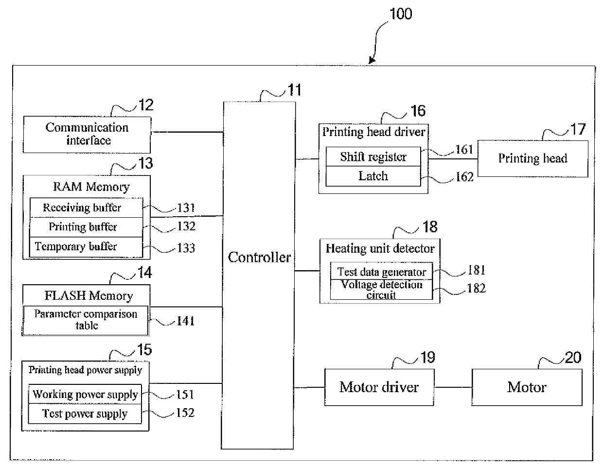
[0038]FIG. 1 is a structure diagram of a printer according to the disclosure, and as shown in FIG. 1, the printer 100 includes a controller 11, a communication interface 12, a Random Access Memory (RAM) 13, a FLASH memory 14, a printing heating power supply 15, a printing head driver 16, a printing head 17, a heating unit detector 18, a motor driver 19 and a motor 20.

[0039]The controller 11 is configured to control each module to execute work, and for example, the controller 11 controls the communication interface 12 to execute data transmission between the printer 100 and a printing request device (such as a computer or network equipment); the controller 11 processes received printing data, and generates dot matrix data to be transmitted to the printing head 17; the controller 11 outputs a control signal for the printing head 17; and the controller 11 controls the motor driver 19 to drive an output shaft of the motor 20 to rotate to drive a printing medium to move in a medium passa...

second embodiment

[0111]FIG. 6 is a flowchart of a method for detecting heating units of a printing head according to the disclosure, and the method includes the following steps:

[0112]Step 61 to Step 64: executing operation the same as that in Step 51 to Step 54.

[0113]Step 65: judging whether a difference between a test voltage Vt provided by a test power supply and a detection voltage Vi is greater than a first preset threshold value or not.

[0114]A controller compares the detection voltage Vi output by the voltage detection circuit with the test voltage Vt provided by the test power supply, and judges whether the difference between the test voltage Vt provided by the test power supply and the detection voltage Vi, i.e. a value of (Vt−Vi), is greater than the first preset threshold value or not, and when the value of (Vt−Vi) is greater than the first preset threshold value, the controller determines that one heating unit of the printing head is in a power-on state after test data Di is transmitted, a...


PUM


Abstract

The disclosure discloses a printer and a method and device for controlling the same. The method for controlling the printer comprises: detecting the number of heating units of a currently mounted printing head; acquiring a resolution, corresponding to the detected number of the heating units, of the printing head; and setting a printer parameter according to the acquired resolution of the printing head. The problem of high error rate after the resolution of the printing head of the printer is changed is solved.

Description

[0001]This invention patent application was submitted to the State Intellectual Property Office on Oct. 15, 2012 with the application number of 201210389788.0, named after “printer and method and device for controlling the same”, and all its contents are combined here as reference.TECHNICAL FIELD OF THE INVENTION[0002]The disclosure relates to the field of printer, in particular to a printer and a method and device for controlling the same.BACKGROUND OF THE INVENTION[0003]At present, a thermal printer is applied more and more widely, multiple heating units arranged in a row at an equal interval along a width direction (hereinafter referred to as horizontal) of a printing head are arranged on the printing head of the thermal printer, and every time when a printing medium is driven to move by a minimum unit length (i.e. one dot line) relative to the printing head along a direction (hereinafter referred to as vertical) perpendicular to the width direction of the printing head, the heat...

Claims


Application Information

Patent Timeline
Patent Type & Authority Patents(United States)
IPC IPC(8): B41J2/165B41J29/38B41J2/335B41J2/36B41J29/393B41J2/35B41J2/315B41J2/32
CPCB41J29/38B41J2/315B41J2/32B41J2/335B41J2/35B41J2/36B41J29/393
Inventor QU, BOWANG, XINDING, JINFENGWANG, BOTAOWANG, XINPING
Owner SHANDONG NEW BEIYANG INFORMATION TECH CO LTD
Why Eureka
Try Eureka