Apparatus for generating high contrast optical signals, and exemplary applications

a technology of optical signals and apparatus, applied in the field of visual indicators, can solve the problems that not all such objects or advantages may be achieved, and achieve the effect of minimising the width of the mark

Inactive Publication Date: 2016-05-10
IMRA AMERICA
View PDF37 Cites 6 Cited by
  • Summary
  • Abstract
  • Description
  • Claims
  • Application Information

AI Technical Summary

Benefits of technology

[0012]An object of the present invention is to provide a display apparatus that generates a high visibility optical signal, such as in the form of an ICON, the ICON comprising a symbol, shape, or other image-like representation. The ICON becomes visible at an observation point during an illumination ON-state. The ICON may be formed in a portion of a display medium, for example as a machined portion of a mirror capable of forming images of a scene by reflection in normal operation in the OFF-state. The visibility of the ICON in the OFF-state, as seen from an observation location corresponding with normal viewing conditions, is sufficiently low such that the normal performance or function of the display medium is maintained.
[0036]The reflective surface of the mirror, or a depthwise portion thereof, can be machined without producing melt or oxidization, resulting in a minimal mark width that is nearly invisible under normal viewing conditions. Varying the depth and / or width can be used to provide additional visual effects, such as gray-scale and intensity variation of the optical signal across an ICON in an ON-state while the ICON is invisible or nearly invisible in the OFF-state.

Problems solved by technology

It is to be understood, however, that not necessarily all such objects or advantages may be achieved in accordance with any particular embodiment.

Method used


Image

  • Apparatus for generating high contrast optical signals, and exemplary applications
  • Apparatus for generating high contrast optical signals, and exemplary applications
  • Apparatus for generating high contrast optical signals, and exemplary applications

Examples


Embodiment Construction

[0047]For the purpose of illustrating various embodiments, terms herein are to be construed as flexible and with ordinary meaning unless otherwise stated. For example, the term “illumination” is not limited to radiant energy in the visible portion of the spectrum, and may include UV, near-far IR, or other wavelengths. An “optical signal” is not limited to visible wavelengths of the electromagnetic spectrum. Similarly, although at least one warning system application considers detection by the human eye at a typical viewing distance, it is to be recognized “detection”, “visibility”, or “invisibility” is not so limited and such conditions may be obtained with the use of imaging devices, pattern recognition algorithms, and the like as pertains to nominal viewing conditions and arrangements for various applications.

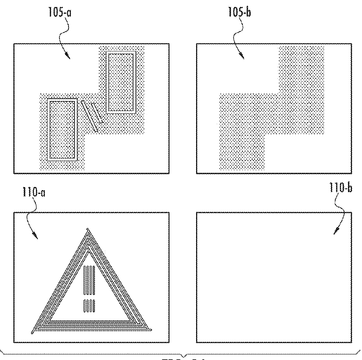
[0048]FIG. 1A schematically illustrates expanded views of a conventional blind spot indicator in ON and OFF states and, for comparison, and corresponding views of a blind spo...


PUM

PropertyMeasurementUnit
sizeaaaaaaaaaa
angleaaaaaaaaaa
widthaaaaaaaaaa

Abstract

A display apparatus generates a high visibility optical signal, such as an ICON, the ICON comprising a symbol, shape, or other image-like representation. The ICON becomes visible at an observation point during an illumination ON-state. The ICON may be formed as a portion of display medium, for example as a machined portion of a mirror capable of forming images of a scene by reflection in normal operation. The visibility of the ICON in the illumination OFF-state from an observation point is sufficiently low such that the normal operation of the display medium is maintained. The display apparatus may be used in a blind spot warning system for a vehicle. Visible wavelength LEDs, RGB LEDs and / or diode lasers may be utilized as an illumination source. Ultrashort laser processing or other methods for material modification may be utilized to form microscopic features which distribute incident light, increasing the visibility of the optical signal at an observation point in an ON-state, with very low visibility in the OFF-state and minimal effect on the image in the display medium in the OFF state.

Description

FIELD OF THE INVENTION[0001]This invention relates to devices, methods, and systems for the generation and display of high contrast optical signals, and more particularly to visual indicators for applications in warning systems. By way of example, the devices may be utilized in blind spot warning systems or similar indicators in vehicles.BACKGROUND OF THE INVENTION[0002]Blind spot warning systems in vehicles may selectively display a graphic representation (ICON) as an indicator of a particular condition of operation. For example, a highly visible optical signal may be generated in a rearview mirror to indicate the presence of a vehicle in a blind spot, or other hazardous condition. Further, turn signal indicators in mirrors, or in the vicinity of mirrors, have been utilized for several years in vehicles. In some systems a warning signal is generated in such a way that the visible light is not in the rearview mirror, but in the interior of the vehicle, for example in the pillar or o...

Claims


Application Information

Patent Timeline
Patent Type & Authority Patents(United States)
IPC IPC(8): B60Q1/00B60Q1/26G02F1/153B60R1/12
CPCB60Q1/00B60R1/1207B60R2001/1215G09G2380/06G09G2380/10
Inventor ARAI, ALAN Y.
Owner IMRA AMERICA
Why Eureka
Try Eureka