Device for dismantling of chosen parts of assembled pallets

a technology for assembled pallets and devices, applied in metal-working equipment, manipulators, metal-working equipment, etc., can solve problems such as extreme compact solutions, and achieve the effect of improving the performance of the third dismantling station in a simple and reliable manner

Active Publication Date: 2016-05-17
YASKAWA NORDIC
View PDF18 Cites 6 Cited by
  • Summary
  • Abstract
  • Description
  • Claims
  • Application Information

AI Technical Summary

Benefits of technology

[0006]By, according to the invention, arranging two dismantling stations on the same support frame, it is rendered possible to optimize the positions of the stations in relation to each other and thus to reduce the distance between them. This can lead to an extremely compact solution. By, according to the invention, using a multiple-axle robot for feeding pallets into and out of the device and also for positioning of the pallets in the device, it is rendered possible thanks to the versatility of the robot to achieve a far greater flexibility than before. Hence, it is easily possible to use the device e.g. for different types of pallets. Further, by, according to the invention, arranging the dismantling stations on a single support frame, it is rendered possible to greatly facilitate the local installation of the device and to facilitate the necessary programming of the robot. The latter is due to the known relative positions of the dismantling stations, which means that no local studies have to be carry out regarding possible motion schemes of the robot, such that the robot can be programmed off-line and in advance.
[0023]In order to improve the performance of the third dismantling station, such as when a stringer board is so badly damaged that it has gone to pieces, preferably an projectable pin each is arranged downstream of both arms of the third dismantling station, said pins being projectable from said plane of the chute and being arranged on such a distance from its associated arm that a stringer board inserted in parallel with the upper end edge of the chute fits freely between said arm and said pin but is jammed in-between if skewed during extraction.

Problems solved by technology

This can lead to an extremely compact solution.

Method used


Image

  • Device for dismantling of chosen parts of assembled pallets
  • Device for dismantling of chosen parts of assembled pallets
  • Device for dismantling of chosen parts of assembled pallets

Examples


first embodiment

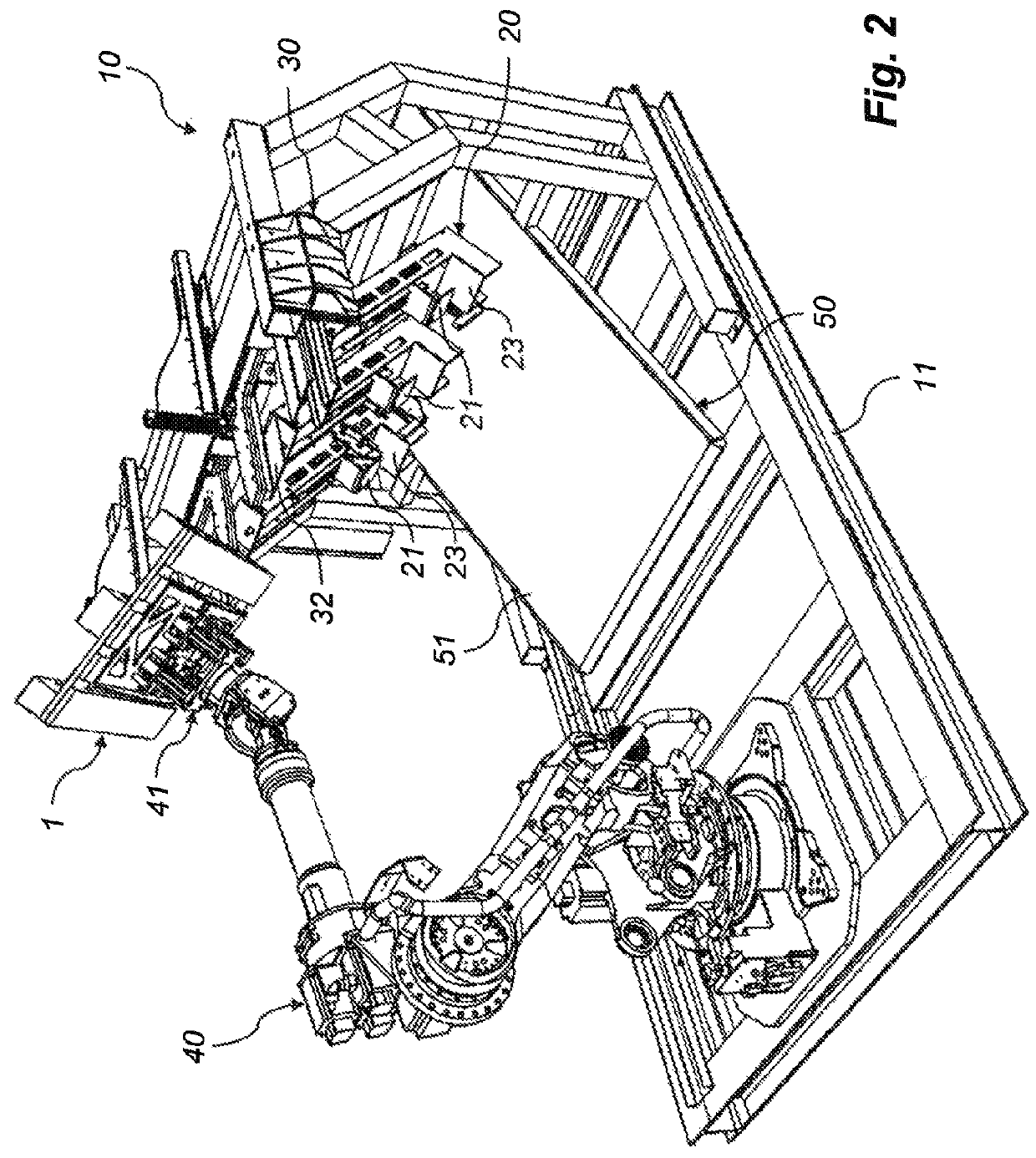
[0036]As can be seen the robot 40 of FIG. 2 is mounted on a support frame 11. According to the device according to the invention, on the same support frame 11 two so-called dismantling stations are to be found, namely a first lower dismantling station 20 and a second upper dismantling station 30. In addition, an output feeder 50, that includes a conveyor 51, is mounted on the support frame 11 under both said dismantling stations 20, 30. The purpose of the output feeder 50 is to use the conveyor belt 51 to catch and feed parts dismantled from pallets out of the device 10, and thus to keep the device free from such parts in order to obtain non-disrupted operation.

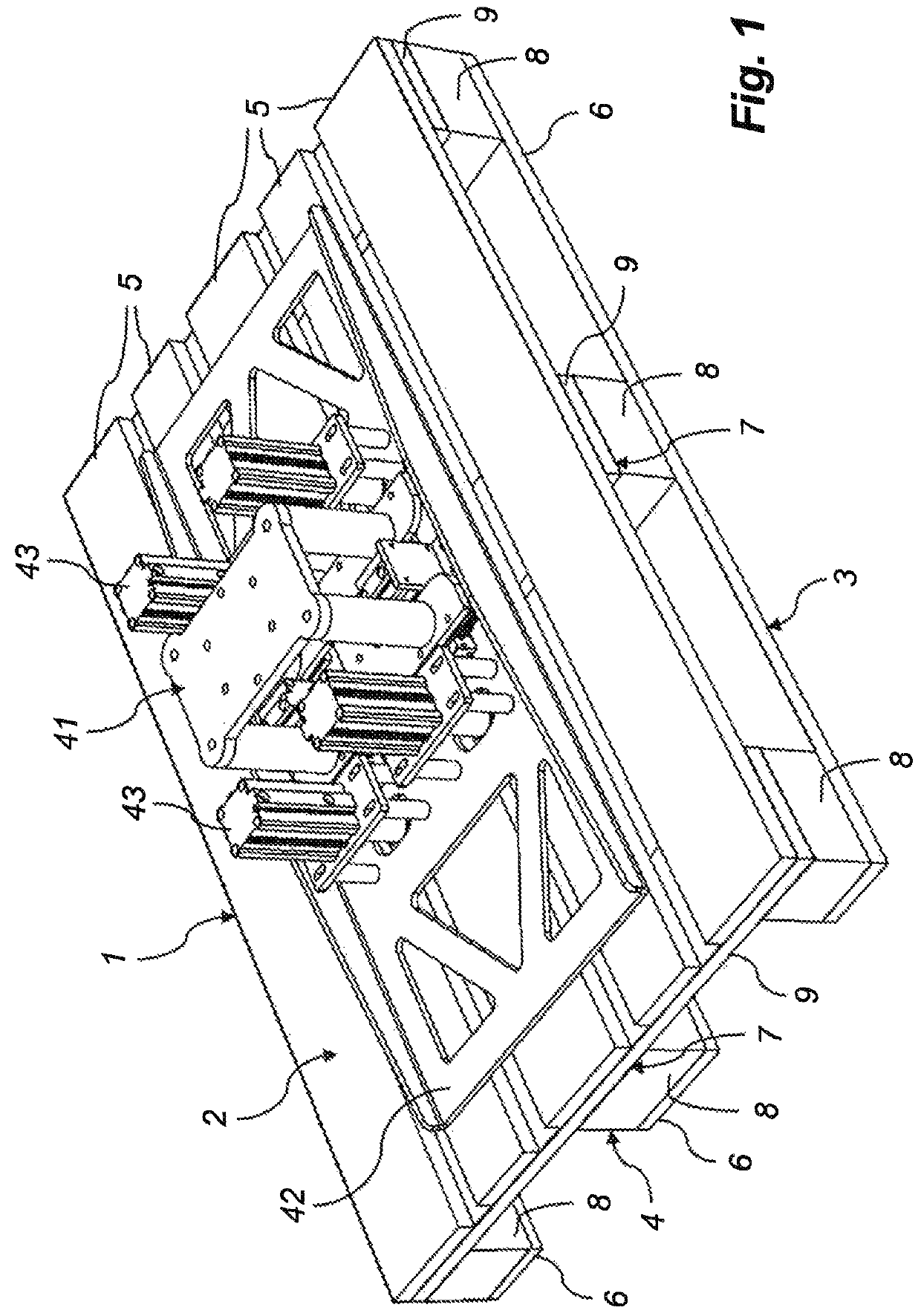
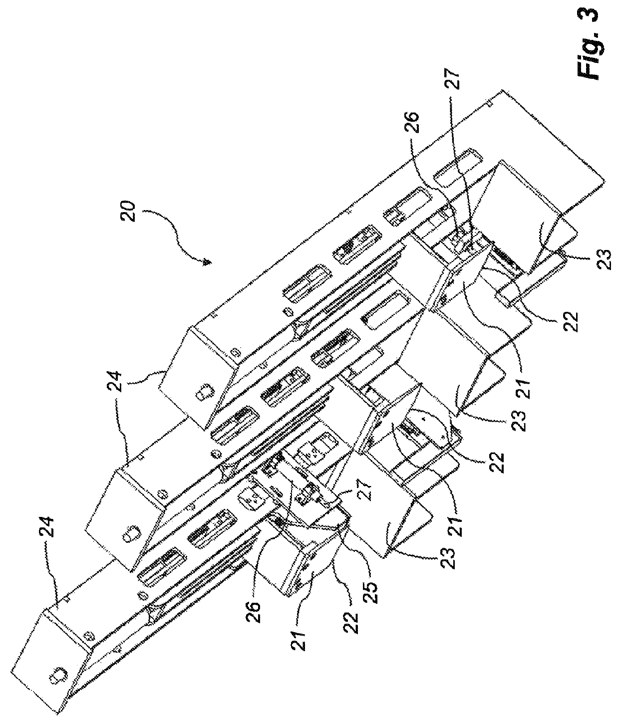
[0037]The first and, as shown, preferably lower dismantling station 20 comprises three knifes 21, which are arranged in a common plane and at center distances in relation to each other corresponding to the center distances of the three blocks 8 along a bottom board 6 of a pallet 1. As can be seen, the knifes 21 are directed o...

second embodiment

[0046]The device 10 of FIG. 6 comprises a third dismantling station 60, in which a pallet 1 is insertable and which, like the other two dismantling stations 20, 30 (not shown in FIG. 6), the robot 40 and the output feeder 50, is carried by the support frame 11 of the device 10. Thus, there the aforementioned advantages of a so-called factory in a box are at hand even with the The third dismantling station 60 comprises an inclined chute 61, that has an upper end edge 62 and a lower end edge 63, that connects to the conveyor 51 of the output feeder 50. Along the upper end edge 62 there are two arms 64 projecting from the plane of the chute 61, wherein said arms can be turned away by means of a cylinder assembly 65, that cooperates with a lever mechanism 66, when services of the third dismantling station 60 are not needed, namely to serve as a catch for extracting by the robot 40 of a stringer board 9, previously separated by means of the second dismantling station 30.

[0047]It has sho...


PUM

PropertyMeasurementUnit
rotationaaaaaaaaaa
distancesaaaaaaaaaa
thicknessaaaaaaaaaa

Abstract

The invention concerns a device for dismantling of chosen parts of assembled pallets, said device including a support frame, that carries a first and a second dismantling station, into which pallets are insertable. The first dismantling station comprises at least one knife, which can be driven in between chosen outer parts of a base of a pallet in order to separate at least some of these parts. The second dismantling station comprises at least one knife, which can be driven in between chosen inner parts of a base of a pallet or between outer parts of a deck of a pallet in order to separate any of these parts. The device also comprises a multiple-axle robot, which is arranged to feed pallets into and out of the device and to position said pallets in relation to the knifes of both dismantling stations of the device.

Description

[0001]This application is the national phase under 35 U.S.C. § 371 of PCT International Application No. PCT / SE2011 / 051386 which has an International filing date of Nov. 18, 2011, which claims priority to Swedish patent application number 1051215-0 filed Nov. 19, 2010.TECHNICAL FIELD[0002]The present invention relates to a device for dismantling of chosen parts of assembled pallets, each comprising a deck layer, which includes parallel deck boards arranged at given distances in relation to each other, a bottom layer, which is in parallel with the deck layer and includes parallel bottom boards, which are arranged at given distances in relation to each other, and an intermediate layer, which is arranged between the deck layer and the bottom layer and includes spacer means, which at given distances in relation to each other are connected to the deck layer and the bottom layer, said device comprising a support frame, carrying a first dismantling station, in which a pallet is insertable, ...

Claims


Application Information

Patent Timeline
Patent Type & Authority Patents(United States)
IPC IPC(8): B23P19/04B25J11/00
CPCB23P19/041B25J11/00Y10T29/534
Inventor BERG, KARL-JOHANMAGNUSSON, BENGTDANIELSSON, PER
Owner YASKAWA NORDIC
Why Eureka
Try Eureka