Power tool with a clamping mechanism for clamping a tool

a technology of power tools and clamping mechanisms, which is applied in the field of hand-held power tools, can solve the problems of increasing the effort required for changing a tool, affecting the operation of tool changing, and affecting the use of the tool, and achieves the effect of convenient tool changing

Active Publication Date: 2016-05-17
C & E FEIN GMBH & CO KG
View PDF10 Cites 5 Cited by
  • Summary
  • Abstract
  • Description
  • Claims
  • Application Information

AI Technical Summary

Benefits of technology

[0007]In view of this, it is a first object of the invention to disclose a hand-held power tool that allows easy tool changing without the use of separate accessories.
[0008]It is a second object of the invention to disclose a hand-held power tool that allows an easy tool changing in a new and ergonomic way.
[0009]It is a third object of the invention to disclose a hand-held power tool that allows for a simplified design of the tool spindle.

Problems solved by technology

Frequently, when a hand-held tool is being used, such separate accessories become lost or are simply left behind, for instance in a toolbox.
As a result, the effort required for changing a tool can be significantly increased.
It has been found, however, that various user groups still perceive the tool changing operation as being relatively awkward.

Method used


Image

  • Power tool with a clamping mechanism for clamping a tool
  • Power tool with a clamping mechanism for clamping a tool
  • Power tool with a clamping mechanism for clamping a tool

Examples


Embodiment Construction

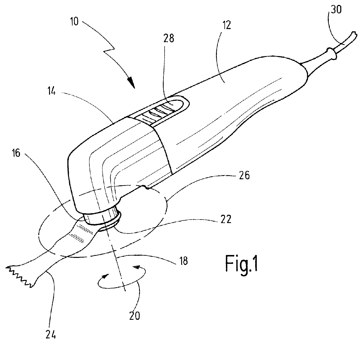
[0073]Represented in FIG. 1 is a hand-held tool that is denoted as a whole by 10. The hand-held tool 10 is a powered hand-held tool, in particular a hand-held tool driven by an electric motor. The hand-held tool 10 is designed as an oscillatory drive. A hand-held tool having a rotary oscillating drive can be used for a multiplicity of sawing tasks, cutting tasks, filling tasks, abrading tasks or similar. Usually, such hand-held tools (oscillating tools) have swivel frequencies in the range from approximately 10 000 to 25 000 oscillations per minute. The oscillations can be effected, for instance, with a small angle of swivel, which is, for example, between 0.5° and 7°.

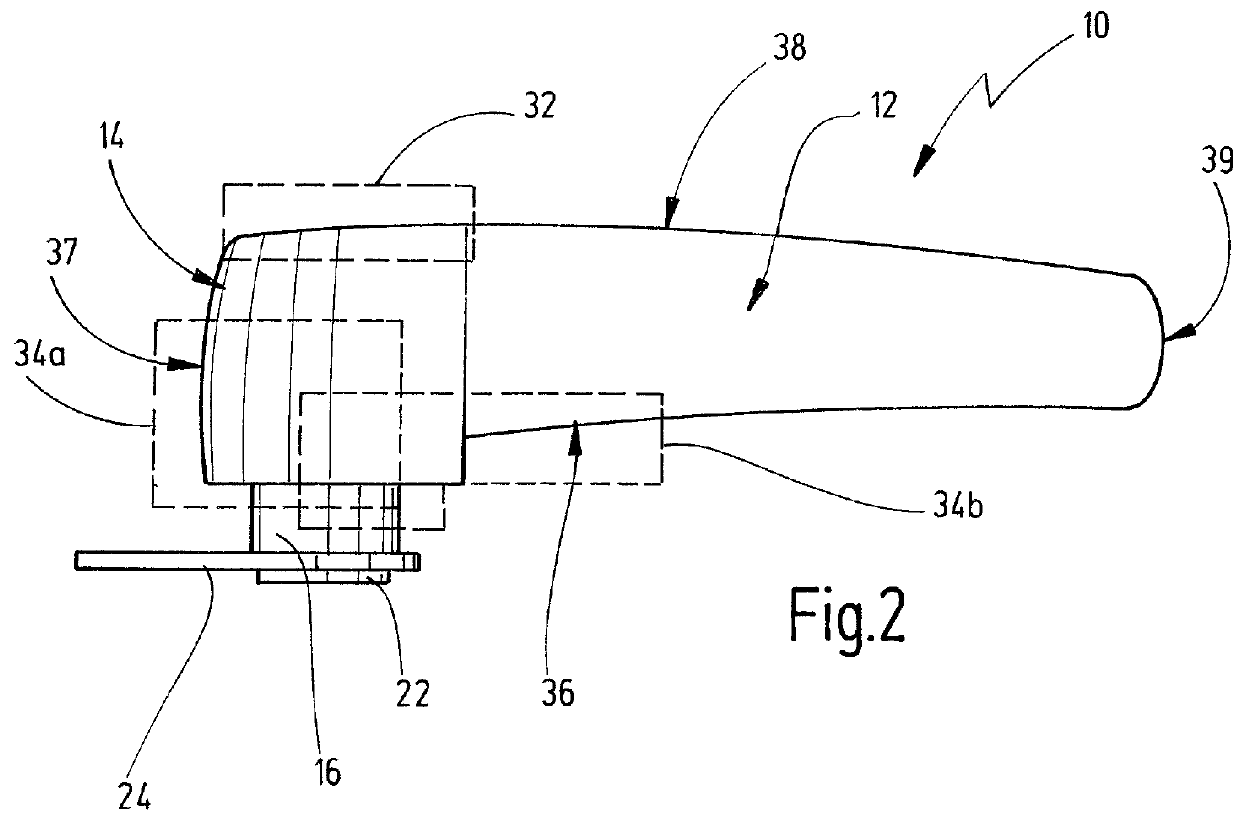
[0074]The hand-held tool 10 has a housing 12, adjoining which there is a spindle head 14. It is understood that the spindle head 14 can be an integral constituent part of the housing 12. It is likewise conceivable for the spindle head 14 to be flange-connected, in the manner of a module, to the housing 12. A force tran...


PUM


Abstract

The invention discloses a hand-held power tool including a housing with a spindle head. A tool spindle can be driven in rotary oscillation about its longitudinal axis and, at its tool-side end, is configured to carry a tool. The tool spindle has a clamping mechanism, which is configured to move a positioning element between a clamping position, in which a tool that is to be carried can be fixed to the tool spindle, and a release position, in which the tool can be released. The clamping mechanism has an actuating mechanism having an actuating element configured as a slide having an engaging surface for axially moving the positioning element to move the clamping mechanism between the clamping and the release positions when the actuating element is moved.

Description

CROSS REFERENCES TO RELATED APPLICATIONS[0001]This application claims priority from German patent application 10 2012 007 927.3, filed on Apr. 17, 2012. The entire content of this priority application is incorporated herein by reference.BACKGROUND OF THE INVENTION[0002]The invention relates to a hand-held power tool, which comprises a housing that has a spindle head, having a tool spindle that can be driven in rotary oscillation about its longitudinal axis and that, at its tool-side end, is configured to carry a tool, the tool spindle being carried in the spindle head at least by means of a drive-side bearing and a tool-side bearing, and having a clamping mechanism, which is configured to move a positioning element between a clamping position, in which a tool that is to be carried can be fixed to the tool spindle, and a release position, in which the tool can be released, the clamping mechanism having an actuating mechanism, which comprises an actuating element that can be coupled t...

Claims


Application Information

Patent Timeline
Patent Type & Authority Patents(United States)
IPC IPC(8): B23B31/19B23Q3/12B24B45/00B27B5/32B24B23/04B24B27/08
CPCB23Q3/12B23B31/19B24B23/04B24B27/08B24B45/006B27B5/32Y10T279/33
Inventor ERNI, ALAIN
Owner C & E FEIN GMBH & CO KG
Why Eureka
Try Eureka