Gantry numerical control machining center and control system and machining method of gantry numerical control machining center

A machining center and gantry technology, applied in general control systems, control/regulation systems, program control, etc., can solve problems such as safety accidents, complex structures, and damage to suction cup mechanisms

Active Publication Date: 2019-08-23
NANXING MACHINERY CO LTD
View PDF8 Cites 4 Cited by
  • Summary
  • Abstract
  • Description
  • Claims
  • Application Information

AI Technical Summary

Problems solved by technology

[0022] In this invention patent, the independently movable vacuum chuck with air lock must have an air lock assembly in order for the vacuum chuck to be positioned at the processing position, and the lock assembly includes an intake piston seat, a piston plate, a piston movable plate, and a wave elastic Washer, two hook plates, two inserts, two insert fixing sleeves, left port block, there are too many parts, the structure is complicated, and the installation is difficult
[0023] The plate adsorption device must include a suction cup loosening mechanism, a moving sliding mechanism, the first air switch and the second air switch, and there are too many parts, the structure is complicated, and the installation is difficult.
[0024] In the above two invention patents, the suction cup cannot be moved automatically, and the suction cup needs to be manually moved to the processing position. The positioning of the suction cup is not accurate, which greatly increases the risk and greatly increases the occurrence of failures
Moreover, if the operator does not operate properly, it is easy to damage the suction cup mechanism, damage the tool, and easily cause safety accidents.

Method used


Image

  • Gantry numerical control machining center and control system and machining method of gantry numerical control machining center
  • Gantry numerical control machining center and control system and machining method of gantry numerical control machining center
  • Gantry numerical control machining center and control system and machining method of gantry numerical control machining center

Examples


Embodiment 1

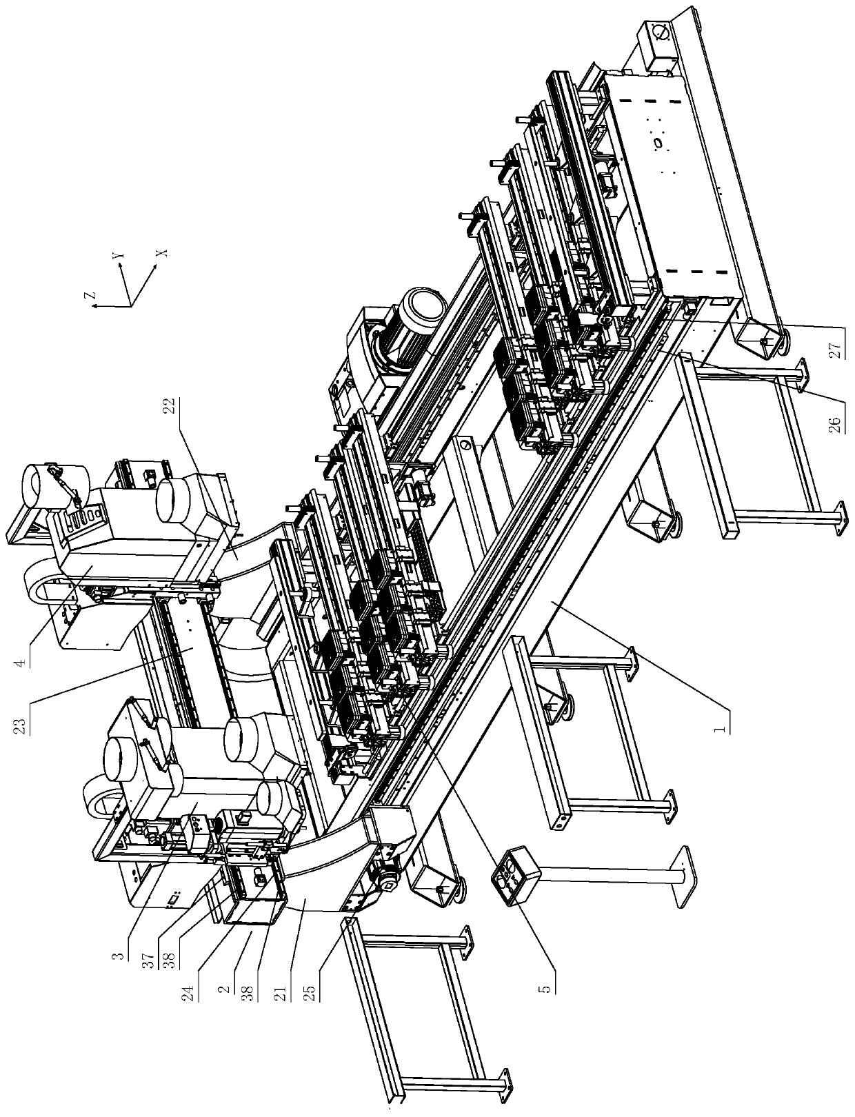
[0146] like figure 1 As shown, a gantry numerical control machining center includes a base 1 , a gantry device 2 , a left machine head 3 , a right machine head 4 , and a workbench device 5 .

[0147] The workbench device 5 is installed on the base 1, and the gantry device 2 is installed together with the base 1 so as to slide back and forth in the X direction; the left machine head 3 and the right machine head 4 are installed on the beam so as to slide back and forth in the Y direction, and are arranged side by side , and placed directly above the workbench device 5 .

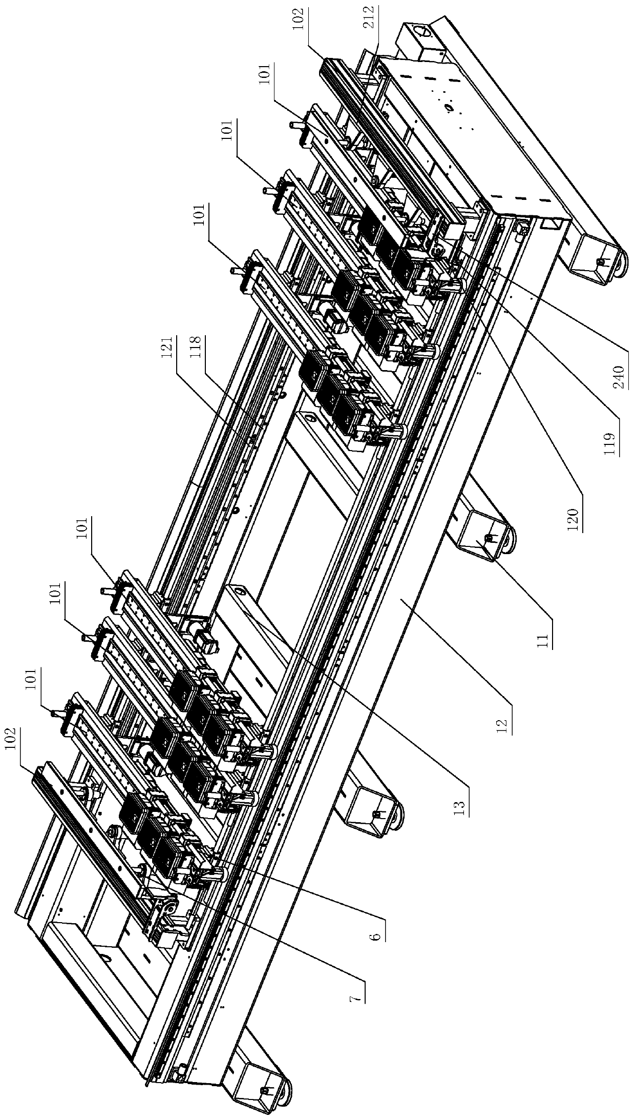
[0148] like figure 2 As shown, the base 1 includes a plurality of square tubes 11 arrayed along the X direction, a square frame-shaped installation frame 12 fixed on the plurality of square tubes 11 , and a Y-direction reinforced square tube 13 fixed inside the installation frame 12 .

[0149] like figure 1 , figure 2 As shown, the gantry device 2 includes a left column 21, a right column 22, and a beam 2...

Embodiment 2

[0221] like Figure 11 As shown, the difference from Embodiment 1 is that each suction cup mechanism includes a suction cup 301, and the vacuum pipeline follows the moving assembly 302.

[0222] The suction cup movement and positioning mechanism utilizes the self-locking function of the suction cup Y-axis feed servo mechanism and the suction cup Y-axis feed transmission mechanism, and can realize the automatic positioning of the suction cup without the air lock component, and can also realize the automatic movement of the suction cup, which not only greatly simplifies structure, but also greatly improved the degree of automation.

Embodiment 3

[0224] like Figure 12 As shown, a control system of a numerical control machining center includes a CNC controller, a data bus, a control bus, and an address bus connected to the CNC controller, a bidirectional control servo control unit connected in parallel to the data bus, the control bus, and the address bus, Left machine head control unit, right machine head control unit, workbench control unit, vacuum control unit, strong and weak current control unit, man-machine dialogue interface unit, communication unit.

[0225] There are multiple standardized CNC controller interfaces on the CNC controller; servo control unit, left machine head control unit, right machine head control unit, workbench control unit, vacuum control unit, strong and weak current control unit, man-machine dialogue The interface unit and communication unit are modules composed of open and modular structures; they have standardized connectors that cooperate with the CNC controller interface, and can be c...


PUM


Abstract

The invention discloses a gantry numerical control machining center and a control system and a machining method of the gantry numerical control machining center. The gantry numerical control machiningcenter comprises a worktable device. The worktable device comprises multiple sets of automatic positioning moving worktable mechanisms which are arranged in the X direction. The gantry numerical control machining center has the beneficial effects that automatic moving positioning of worktables and suckers can be achieved. The control system comprises a CNC controller, a servo control unit in parallel connection with a bus in a bidirectional control manner, a machine head control unit, a worktable control unit and a vacuum control unit. The worktable control unit comprises multiple sets of automatic positioning moving worktable control units and X-direction positioning control units. Each set of automatic positioning moving worktable control unit comprises a set of worktable X-axis feedingservo system, multiple sets of sucker Y-axis feeding servo systems and a Y-direction positioning control unit. The worktable X-axis feeding servo systems and the sucker Y-axis feeding servo systems are connected with a bus of a PLC in parallel. The control system has the beneficial effects that universality is achieved, compatibility is high, and transportability is high.

Description

technical field [0001] The invention relates to the field of large-scale precision numerical control machine tools in the field of processing wood and similar boards, in particular to a gantry numerical control machining center with a high-grade numerical control system for processing wood, and its control system and processing method. Background technique [0002] With the emergence of microprocessors, the world has entered a new era of numerical control, and the multi-axis control machine tools that can only be realized by computers have risen rapidly, bringing wood processing into an era of automation and intelligence. field of application is becoming more and more common. [0003] In the prior art, the CNC wood processing center can complete the engraving and milling, vertical drilling, and grooving processes. With the help of the wood processing center, the wood can be processed conveniently and the production efficiency can be improved. However, after the wood is engr...

Claims


Application Information

Patent Timeline
Patent Type & Authority Applications(China)
IPC IPC(8): B27C9/04G05B19/402
CPCB27C9/04G05B19/402
Inventor 徐淦赖正友秦振伟容世桢韦国平李吉波
Owner NANXING MACHINERY CO LTD
Why Eureka
Try Eureka