Ejection port cover for a firearm

a technology for ejection port covers and firearms, which is applied in the direction of firearms, cartridge extractors, shoulder-fired small arms, etc., can solve the problems of more gas to vent out, pain and discomfort, and skin discoloration, and avoid distraction. cost, the effect of increasing the amount of gas

Active Publication Date: 2016-05-17
GEAR HEAD WORKS LLC
View PDF12 Cites 27 Cited by
  • Summary
  • Abstract
  • Description
  • Claims
  • Application Information

AI Technical Summary

Benefits of technology

[0013]One aspect of the disclosure is a device for covering an ejection port of a firearm, the firearm including a receiver having an interior side and an exterior side, the ejection port defined in the receiver, the ejection port having an upper peripheral edge and a notch defined in the upper peripheral edge of the ejection port. The device includes a backing member positionable across the ejection port from the interior side of the receiver; a cover positionable over the ejection port from the exterior side of the receiver; and a fastener extending between the backing member and the cover, the fastener selectively tightening the backing member and the cover together to clamp the cover over the ejection port. The cover is sealingly positioned over the notch in the ejection port when the cover is clamped over the ejection port. As such, the device can help prevent or block gas, heat, and residue from passing through the ejection port and contacting an operator's face and eyes.
[0015]Another aspect of the present disclosure is an accessory for a firearm including a backing member positionable across an ejection port defined in a receiver of a firearm from an interior side of the receiver, the ejection port having an upper peripheral edge and a notch defined in said upper peripheral edge; a cover positionable over the ejection port from an exterior side of the receiver; a fastener extending between the backing member and the cover, the fastener being operable to selectively tighten the backing member and the cover together to clamp the cover over the ejection port; and a sling swivel socket defined in the cover. The cover can block gas in the receiver from passing through the notch in the ejection port when the cover is clamped over the ejection port.
[0016]One objective of the present disclosure is to help prevent hot gas and powder residue from escaping through the ejection port of a firearm. Another aspect of the present disclosure is to help keep gas, heat, powder residue and other particulate matter out of the face of an operator using a firearm. Still yet another aspect of the present disclosure is to cover a notch in an ejection port of a firearm.

Problems solved by technology

However, high-pressure gases, heat, and powder residue are also often released through the ejection port during operation of such firearms.
In some firearms, the ejection port is positioned in the receiver such that some portion of the gas, heat and powder residue is allowed to escape through the ejection port and contact an operator's face and eyes, causing pain and discomfort, distraction, and skin discoloration.
This problem can be exacerbated by use of a sound suppressor, which can cause even more gas to vent out of the ejection port defined in the receiver.
The release of gas and particulate matter through the ejection port and into an operator's face and eyes during use of the firearm can be a dangerous distraction and hindrance, particularly during periods of repeat or sustained fire, as the resulting discomfort may require the operator to cease firing or look away from a target or threat in order to alleviate the problem.
Such a distraction can be costly during combat and other life threatening situations where visual acuity, timing and accuracy are critical.
The conventional ejection port cover does nothing to prevent gas and powder residue from escaping out of the unused ejection port nearest the operator's face and allows hot gas and powder residue to vent through such ejection port directly into the face of the operator.

Method used


Image

  • Ejection port cover for a firearm
  • Ejection port cover for a firearm
  • Ejection port cover for a firearm

Examples


Embodiment Construction

[0032]While the making and using of various embodiments of the present invention are discussed in detail below, it should be appreciated that the present invention provides many applicable inventive concepts that are embodied in a wide variety of specific contexts. The specific embodiments discussed herein are merely illustrative of specific ways to make and use the invention and do not delimit the scope of the invention. Those of ordinary skill in the art will recognize numerous equivalents to the specific apparatus and methods described herein. Such equivalents are considered to be within the scope of this invention and are covered by the claims.

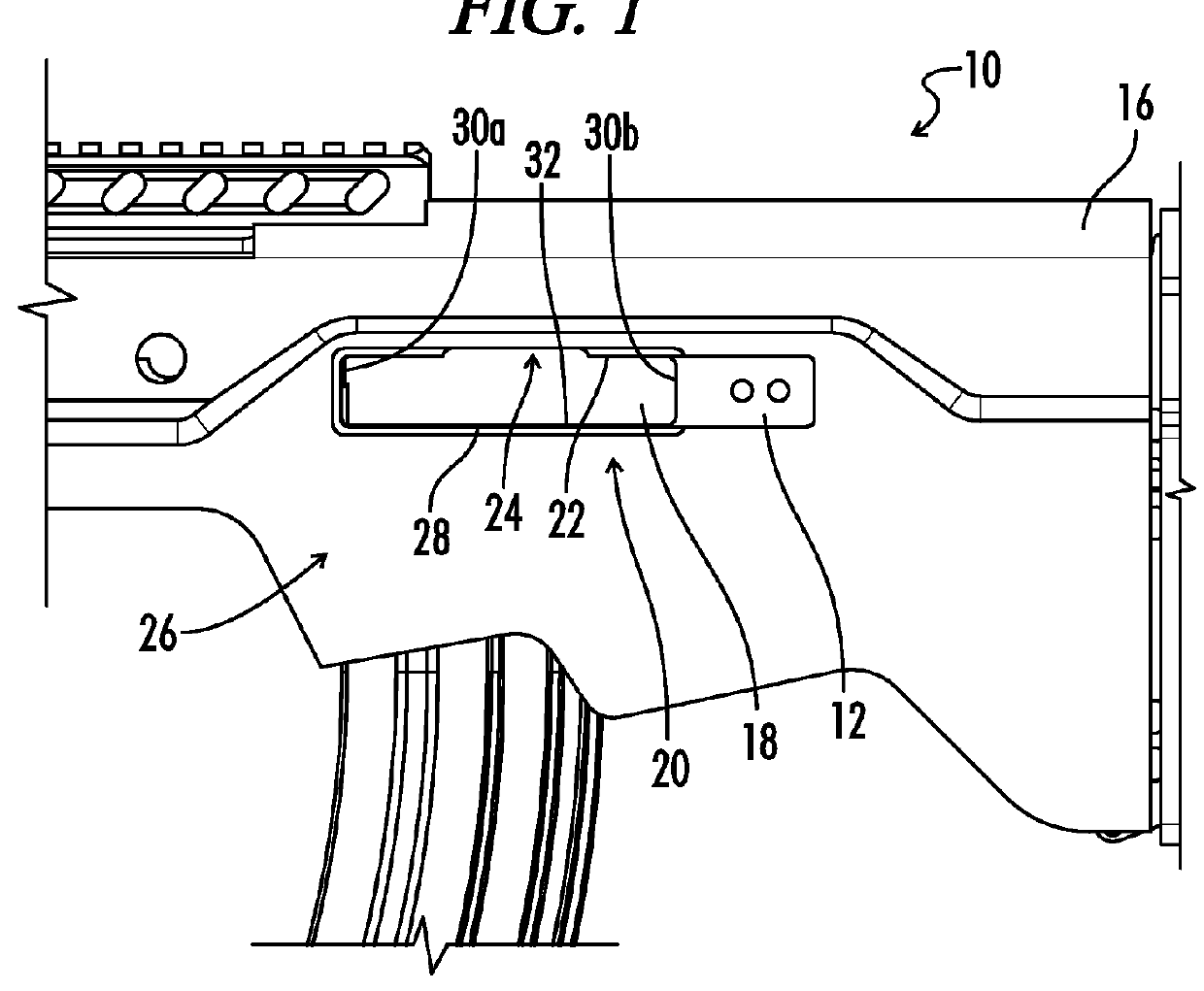
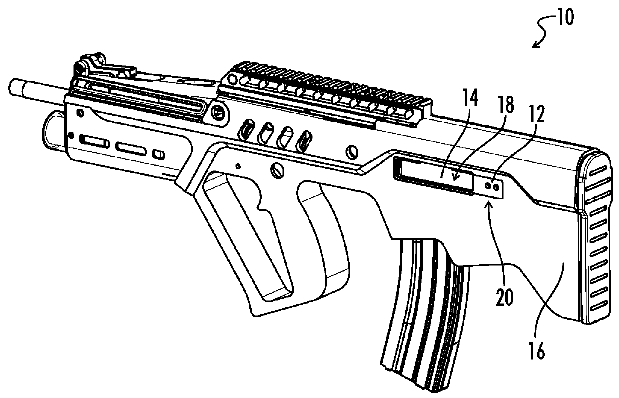
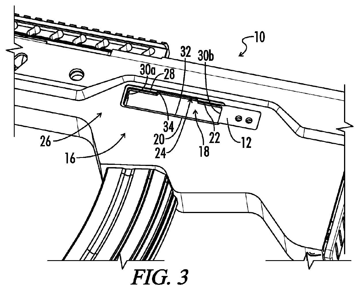
[0033]In the drawings, not all reference numbers are included in each drawing, for the sake of clarity. In addition, positional terms such as “upper,”“lower,”“side,”“top,”“bottom,” etc. refer to the apparatus when in the orientation shown in the drawing. A person of skill in the art will recognize that the apparatus can assume different or...


PUM


Abstract

A device for covering a firearm ejection port, the firearm including a receiver having an interior and an exterior side, the ejection port defined in the receiver, the ejection port having an upper peripheral edge and a notch defined in the upper peripheral edge. The device includes a backing member positionable across the ejection port from an interior side of the receiver. A cover is positionable over the ejection port from an exterior side of the receiver. A fastener extends between the backing member and the cover, the fastener being operable to selectively tighten the backing member and the cover together to clamp the cover over the ejection port. The cover is positioned over the notch in the ejection port when the cover is clamped over the ejection port to prevent gas in the receiver from passing through the notch.

Description

CROSS-REFERENCES TO RELATED APPLICATIONS[0001]This application claims priority to and hereby incorporates by reference in its entirety U.S. Provisional Patent Application Ser. No. 62 / 045,725 entitled GAS SEALING EJECTION PORT COVER, filed on Sep. 4, 2014.[0002]A portion of the disclosure of this patent document contains material that is subject to copyright protection. The copyright owner has no objection to the reproduction of the patent document or the patent disclosure, as it appears in the U.S. Patent and Trademark Office patent file or records, but otherwise reserves all copyright rights whatsoever.STATEMENT REGARDING FEDERALLY SPONSORED RESEARCH OR DEVELOPMENT[0003]Not ApplicableREFERENCE TO SEQUENCE LISTING OR COMPUTER PROGRAM LISTING APPENDIX[0004]Not ApplicableBACKGROUND OF THE INVENTION[0005]The present disclosure relates generally to ejection port covers for firearms and more specifically to ejection port covers having one or more dynamic sealing characteristics.[0006]Man...

Claims


Application Information

Patent Timeline
Patent Type & Authority Patents(United States)
IPC IPC(8): F41A35/02
CPCF41A35/02F41A15/00F41C7/00
Inventor REAVIS, III, JOHNSON PAUL
Owner GEAR HEAD WORKS LLC
Why Eureka
Try Eureka