
Motion analyzing apparatus and motion analyzing program

a technology of motion analysis and motion plane, which is applied in the field of motion analysis apparatus and motion analysis program, can solve the problems of time-consuming display of swing plane and large difference in actual swing plane, and achieve the effect of presenting a clear index for analysis

Active Publication Date: 2016-05-17
SEIKO EPSON CORP
View PDF9 Cites 9 Cited by
  • Summary
  • Abstract
  • Description
  • Claims
  • Application Information

AI Technical Summary

Benefits of technology

The invention provides a device and program for analyzing motion by creating a clear index for analysis. Additionally, it allows for easy specification of a virtual plane and the initial position of a first line segment in the stationary state using the output from inertial sensors. This makes it possible to accurately analyze the position changes of the first line segment during a swing.

Problems solved by technology

Accordingly, there are problems that a difference from the actual swing plane is larger and display of the swing plane takes time.
Regarding Patent Document 2, the operation of editing image data is necessary, and there are the same problems as those of Patent Document 1.
However, in the methods of Patent Documents 1 and 2, for example, to obtain the hogan plane, there has been no other way to take the figure of the golfer at address from behind and draw lines by hand using a scale or the like based on the taken image.
Therefore, in golf swing analysis, there has no mean for simply and accurately presenting the impact line, shaft plane, or hogan plane to the golfer.

Method used


Image

  • Motion analyzing apparatus and motion analyzing program
  • Motion analyzing apparatus and motion analyzing program
  • Motion analyzing apparatus and motion analyzing program

Examples


first embodiment

(1) Configuration of Golf Swing Analyzing Apparatus

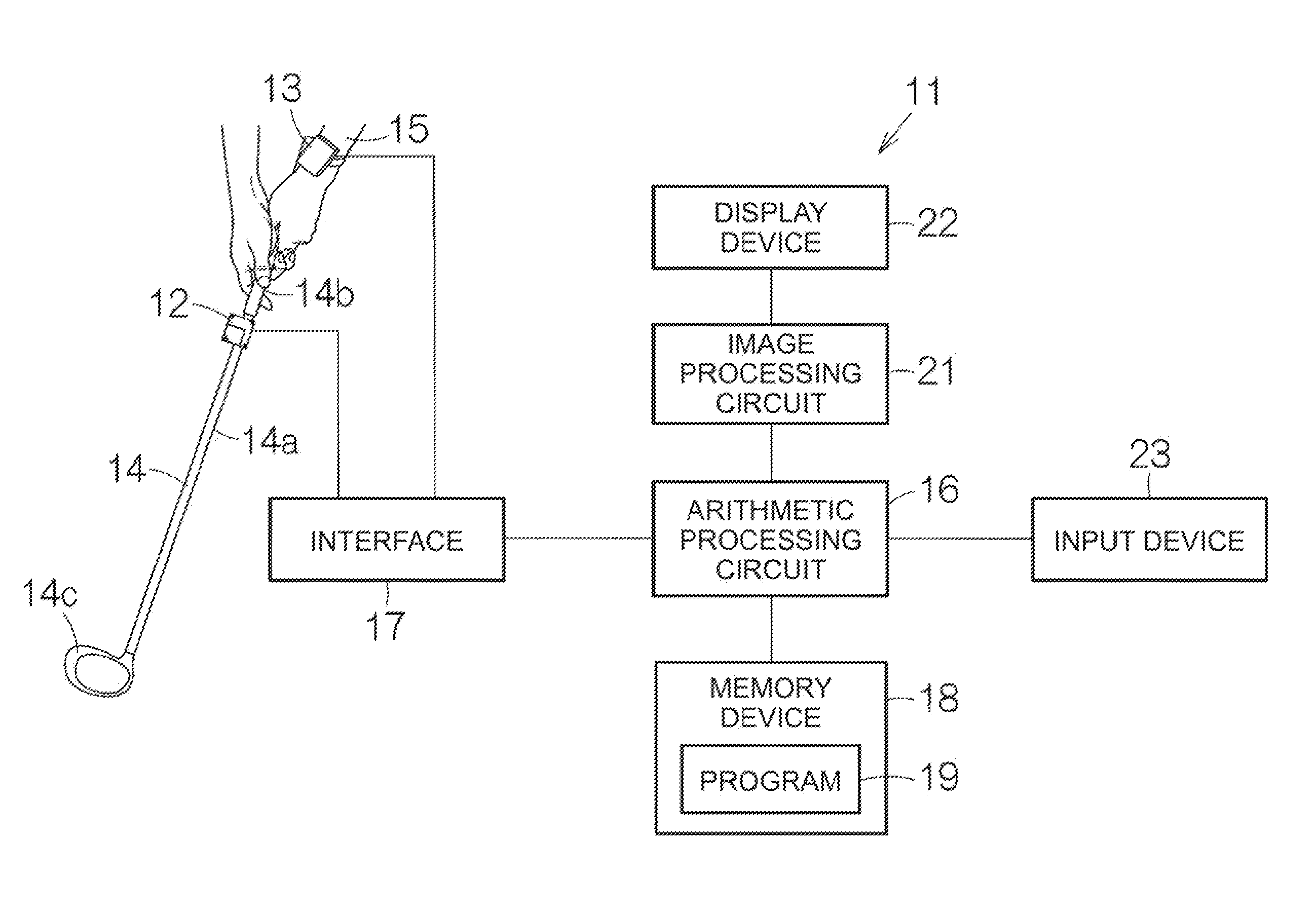
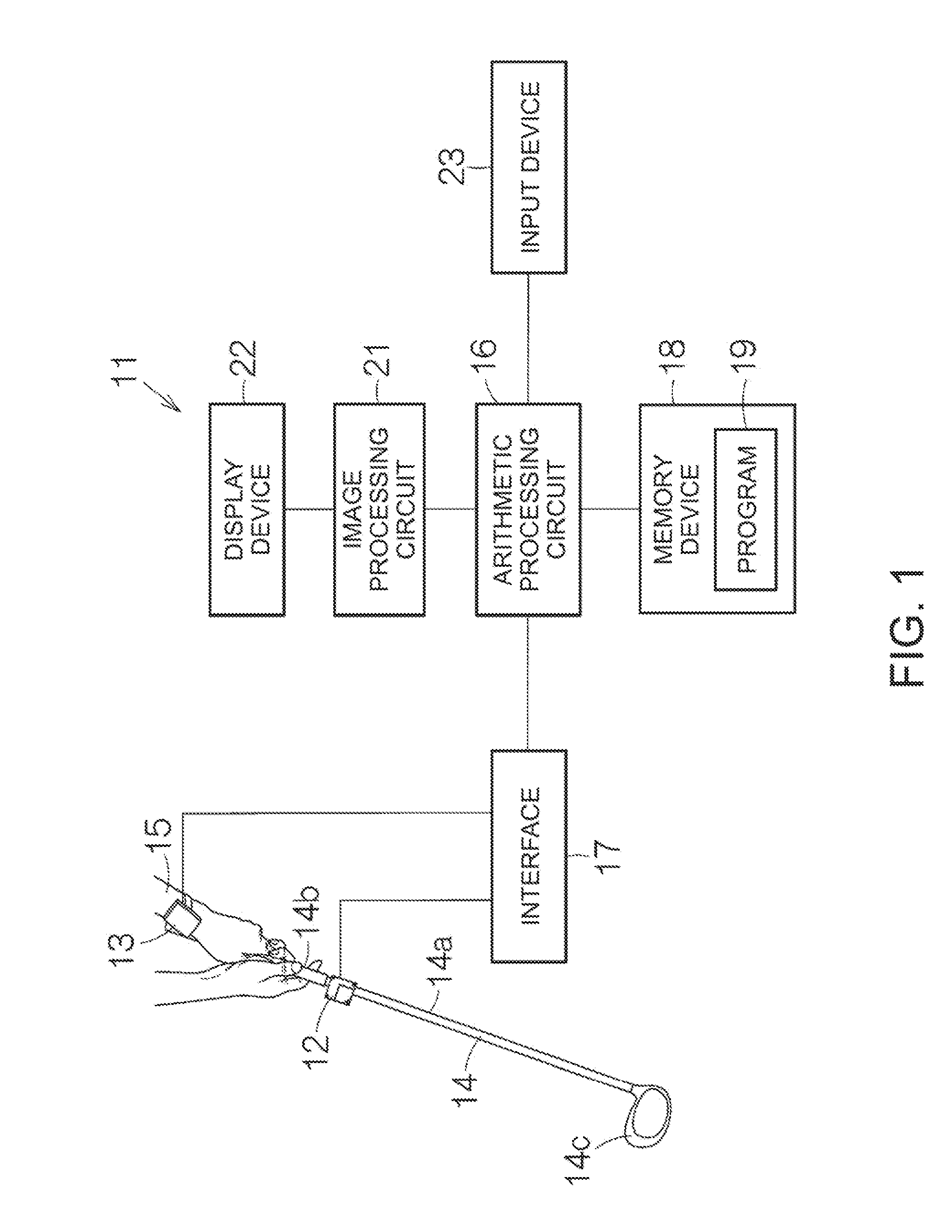
[0048]FIG. 1 schematically shows a configuration of a golf swing analyzing apparatus (motion analyzing apparatus) 11 according to the first embodiment of the invention. The golf swing analyzing apparatus 11 includes, e.g., a first inertial sensor 12 and a second inertial sensor 13. An acceleration sensor and a gyro sensor are incorporated in each of the first and second inertial sensors 12, 13. The acceleration sensor can individually detect accelerations generated in directions of orthogonal three axes. The gyro sensor can individually detect angular velocities around the respective three orthogonal axes. The first and second inertial sensors 12, 13 output detection signals. The acceleration and the angular velocity are specified with respect to each axis by the detection signals. The acceleration sensor and the gyro sensor detect information of the accelerations and the angular velocities. The second inertial sensor 13 is attached...

second embodiment

(5) Configuration of Golf Swing Analysis

[0090]FIG. 12 schematically shows a configuration of a golf swing analyzing apparatus 11a according to the second embodiment. In the golf swing analyzing apparatus 11a, the second inertial sensor 13 is omitted compared to the golf swing analyzing apparatus 11 according to the first embodiment. That is, for the analysis of golf swing, a single inertial sensor, i.e., the first inertial sensor 12 is used. An arithmetic processing circuit 16a is replacing the arithmetic processing circuit 16 according to the first embodiment. A location calculation unit 51a replacing the location calculation unit 51 has the first line segment calculation part 51A, but does not have the third line segment calculation part 51B. The hogan plane image data generation unit 53 is replaced by a hogan plane image data generation unit 53a.

[0091]As shown in FIG. 13, the shaft plane image data generation unit 52 has the same configuration as that described above. On the oth...


PUM


Abstract

A motion analyzing apparatus includes a first calculation unit that calculates a position of a first line segment representing a direction in which a rod-like part of a sporting tool extends in a stationary state, a second calculation unit that calculates the position of the first line segment at hitting, and a third calculation unit that specifies a virtual plane formed by the first line segment in the stationary state and a second line segment representing a ball hitting direction, wherein a relation between the virtual plane and the first line segment at the hitting is compared.

Description

BACKGROUND[0001]1. Technical Field[0002]The present invention relates to a motion analyzing apparatus, a motion analyzing program, etc.[0003]2. Related Art[0004]For example, in golf as a specific example of motion, a concept of swing plane is generally known. The swing plane corresponds to a trace of a golf club at swing. For example, in Patent Document 1 (JP-A-2009-20897) and Patent Document 2 (JP-A-2008-23036), a golf swing of a subject is taken by a camera or the like from behind of the subject and the swing plane is specified from the taken image.[0005]A method of obtaining the swing plane in Patent Document 1 is obtaining at least two specific points in swing from image data and analyzing a swing plane from the two points. In the method, first, it is necessary to edit image data after the end of swing and perform operation of obtaining the specific points. Accordingly, there are problems that a difference from the actual swing plane is larger and display of the swing plane take...

Claims


Application Information

Patent Timeline
Patent Type & Authority Patents(United States)
IPC IPC(8): G09B19/00A63B69/36
CPCG09B19/0038A63B69/3632A63B2220/13A63B2220/40A63B2220/833
Inventor SATO, MASAFUMI
Owner SEIKO EPSON CORP
Learn More