Wide-angle optical unit for ophthalmological implants

a technology of optical units and ophthalmological implants, applied in the field of optical units and optical systems, can solve the problems of limited vision field of potential patients, severe impairment of peripheral vision of patients in vertical and horizontal directions, and inability to use conventional wide-angle systems and optical systems containing said wide-angle systems on their own

Active Publication Date: 2016-05-24
KARLSRUHER INST FUR TECH
View PDF9 Cites 21 Cited by
  • Summary
  • Abstract
  • Description
  • Claims
  • Application Information

AI Technical Summary

Benefits of technology

[0032]An alternative embodiment provides an annular prism which allows relative movements with respect to a proximal-side shifting lens (or alternatively a lens system or a lens having a variable refractive power). The annular prism is not rigidly connected to the shifting lens, but rather is preferably an integral component of for example the exit window on the housing side, yet surrounds all or part of the peripheral boundary surface of the proximal shifting lens. The shiftability between the shifting lens and the annular prism achieves a field of vision that varies with the shifting and is detectable by the retina.

Problems solved by technology

Owing to their geometric and optical basic parameters, such as the miniaturisation required as a result of the dimensions in the eye, most complex optical systems, such as that described above, which are implanted in the eye in place of or in addition to the human lens, greatly restrict the field of vision of the potential patient.
This means in particular that the peripheral vision of the patient in the vertical and horizontal directions is severely impaired when a complex structure is implanted.
Conventional wide-angle systems and optical systems containing said wide-angle systems on their own are not suitable for use in the human eye, since the idea behind them is to project the wide-angle range in the object plane onto a defined, small region in the image plane (film, camera chip).

Method used


Image

  • Wide-angle optical unit for ophthalmological implants
  • Wide-angle optical unit for ophthalmological implants
  • Wide-angle optical unit for ophthalmological implants

Examples


Embodiment Construction

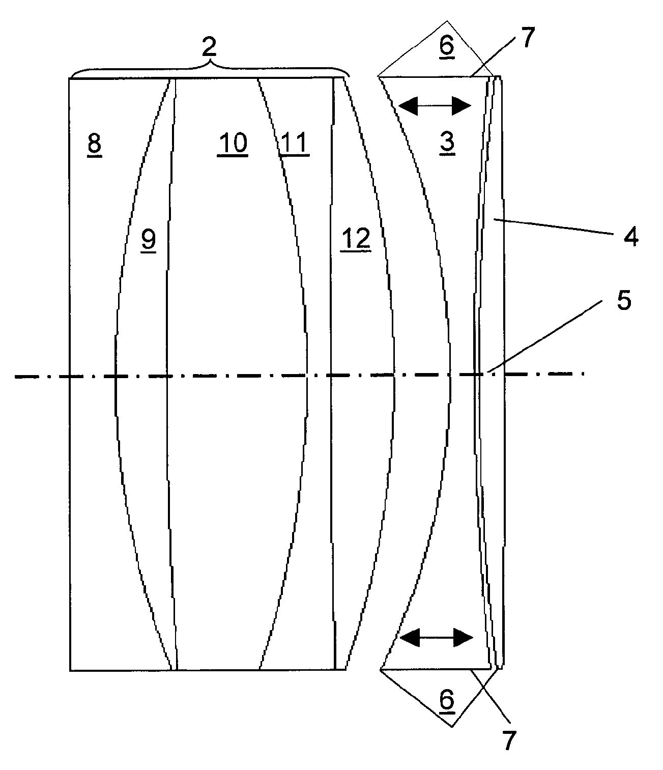
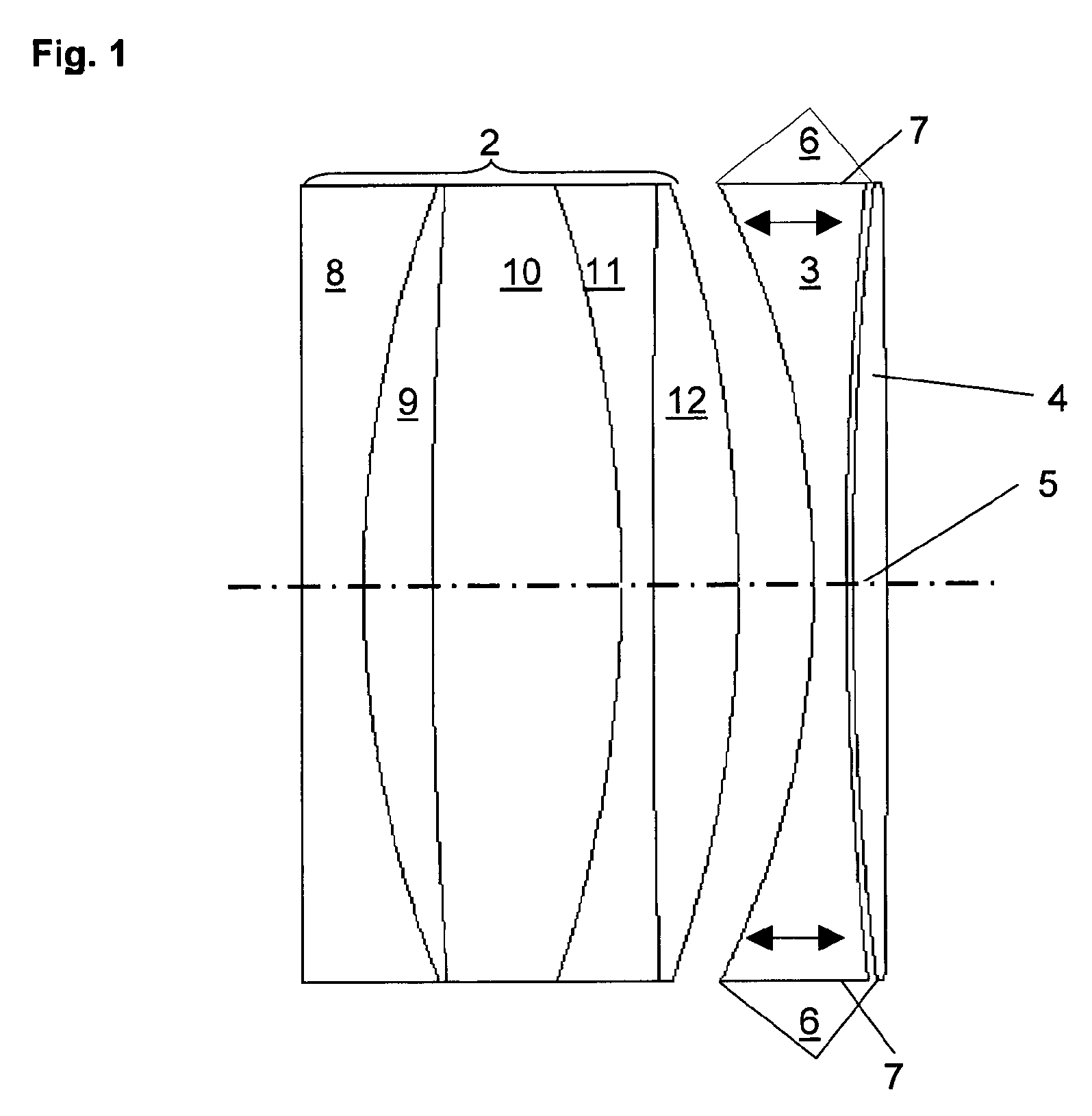
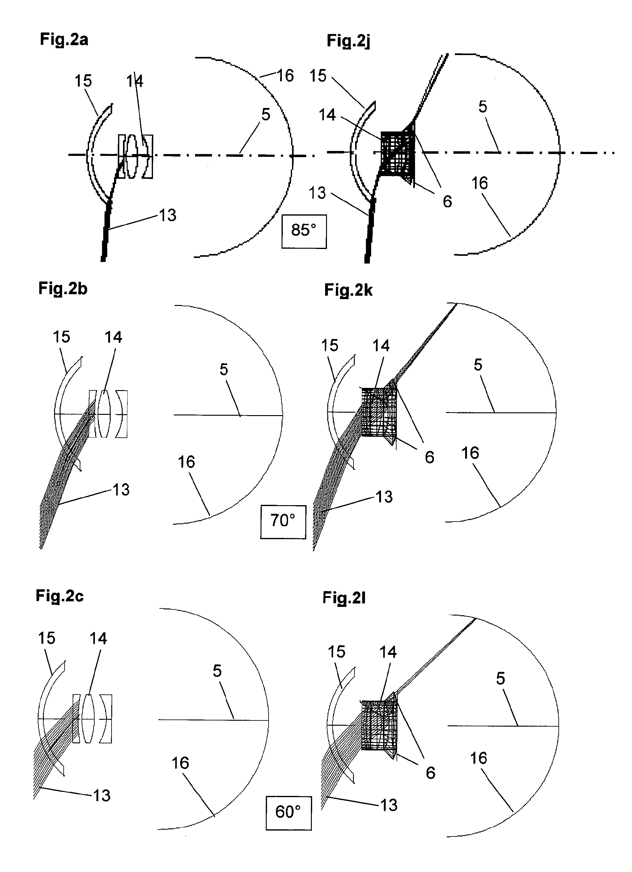
[0013]The wide-angle optical unit is a component of a preferably ophthalmological implant for restoring the accommodative ability. Said unit comprises an optical unit having a high angular acceptance, and a decoupling structure. Said unit does not necessarily comprise the optical adjustment mechanism of the accommodation system. Together with the optical adjustment mechanism and optionally separate emergent surfaces or emergent components, the wide-angle optical unit forms an optical system.

[0014]An embodiment of the invention provides a wide-angle optical unit for ophthalmological implants in the eye, which, owing to their design and structure, restrict the field of vision of the patient, such that said optical unit does not restrict sight in a central field of view and at the same time ensures the implant wearer has peripheral vision.

[0015]A wide-angle optical unit of an optical system for ophthalmological implants in the eye is provided herein according to one embodiment of the i...


PUM


Abstract

A wide-angle optical unit for ophthalmological implants in the eye includes a lens system arranged in a rotationally symmetrical manner about an optical axis and further includes at least two lenses that rest one on top of the other in a planar manner and which are made of materials having different optical refractive indices. In addition, the wide-angle optical unit includes an optical decoupling structure and a trailing lens arranged proximally with respect to the interior of the eye. The trailing lens is mounted around the optical decoupling structure.

Description

CROSS-REFERENCE TO RELATED APPLICATIONS[0001]This application is a U.S. National Phase application under 35 U.S.C. §371 of International Application No. PCT / EP2013 / 002139 (WO 2014 / 015964 A1), filed on Jul. 18, 2013, and claims benefit to German Patent Application No. DE 10 2012 106 653.1, filed Jul. 23, 2012.FIELD[0002]The invention relates to optical units and optical systems, and in particular, to wide angle optical units and to wide-angle optical systems including such wide angle optical units for ophthalmological implants.BACKGROUND[0003]In ophthalmology, ophthalmological implants are used for restoring and maintaining sight. Examples of simple implants are artificial eye lenses, which replace the endogenous eye lens, by means of exchange, for example when said endogenous eye lens opacifies in the event of a grey cataract. Lenses of this type comprise one single lens. Bifocal or multifocal lenses having two or more fixed focal lengths installed in parallel are also known in opht...

Claims


Application Information

Patent Timeline
Patent Type & Authority Patents(United States)
IPC IPC(8): A61F2/16
CPCA61F2/1648A61F2/1629A61F2/1656A61F2002/1699
Inventor SIEBER, INGOGUTH, HELMUTBRETTHAUER, GEORGGENGENBACH, ULRICHGUTHOFF, RUDOLF F.
Owner KARLSRUHER INST FUR TECH
Why Eureka
Try Eureka