Supercharge Your Innovation With Domain-Expert AI Agents!

Fixing plate of a mold of an injection molding apparatus for plastic material

a technology for fixing plates and plastic materials, which is applied in the field of plastic material injection molding apparatuses, can solve the problems of high direct and indirect costs, inconvenient access, and considerable high dimensions of fixing plates, and achieve the effect of reducing costs and overall dimensions

Active Publication Date: 2016-05-24
INGLASS SPA
View PDF6 Cites 14 Cited by
  • Summary
  • Abstract
  • Description
  • Claims
  • Application Information

AI Technical Summary

Benefits of technology

The solution effectively protects actuator components from heat, simplifies construction, reduces the apparatus' overall dimensions, and facilitates easy maintenance, eliminating the need for cooling systems and improving accessibility.

Problems solved by technology

This arrangement, as well as other solutions in which the actuator means envisage an electric motor directly mounted on the distributor, can lead to problems caused by the temperature of the distributor itself, both in terms of the mechanical profile, in relation to the rotating members, and the electrical profile, relative to the coils of the motor and its electronic components, as well as regarding the relative wiring subjected to premature aging and consequent rupture, or even fusion, of the relative casing.
In these cases, it is necessary to replace the damaged parts, whose accessibility may be inconvenient, with the possible consequence of non-negligible operational pauses of the molding apparatus, as well as high direct and indirect costs.
These configurations all have the same drawback: considerably high dimensions of the fixing plate of the mold regarding the thickness, which implicates a corresponding considerable bulk of the molding apparatus as a whole.
In addition, access to the actuators of the injectors, for example for maintenance or replacement, is usually complicated and inconvenient.
In this case, however, the injectors of the molding apparatus are not of the obturator-type, i.e. they are not associated with respective electric, or other types of, actuators, so that neither the problem of the separation of the actuators from the distributor arises, nor the problem relative to the bulk of the fixing plate deriving from the presence of actuators.

Method used


Image

  • Fixing plate of a mold of an injection molding apparatus for plastic material
  • Fixing plate of a mold of an injection molding apparatus for plastic material
  • Fixing plate of a mold of an injection molding apparatus for plastic material

Examples


Embodiment Construction

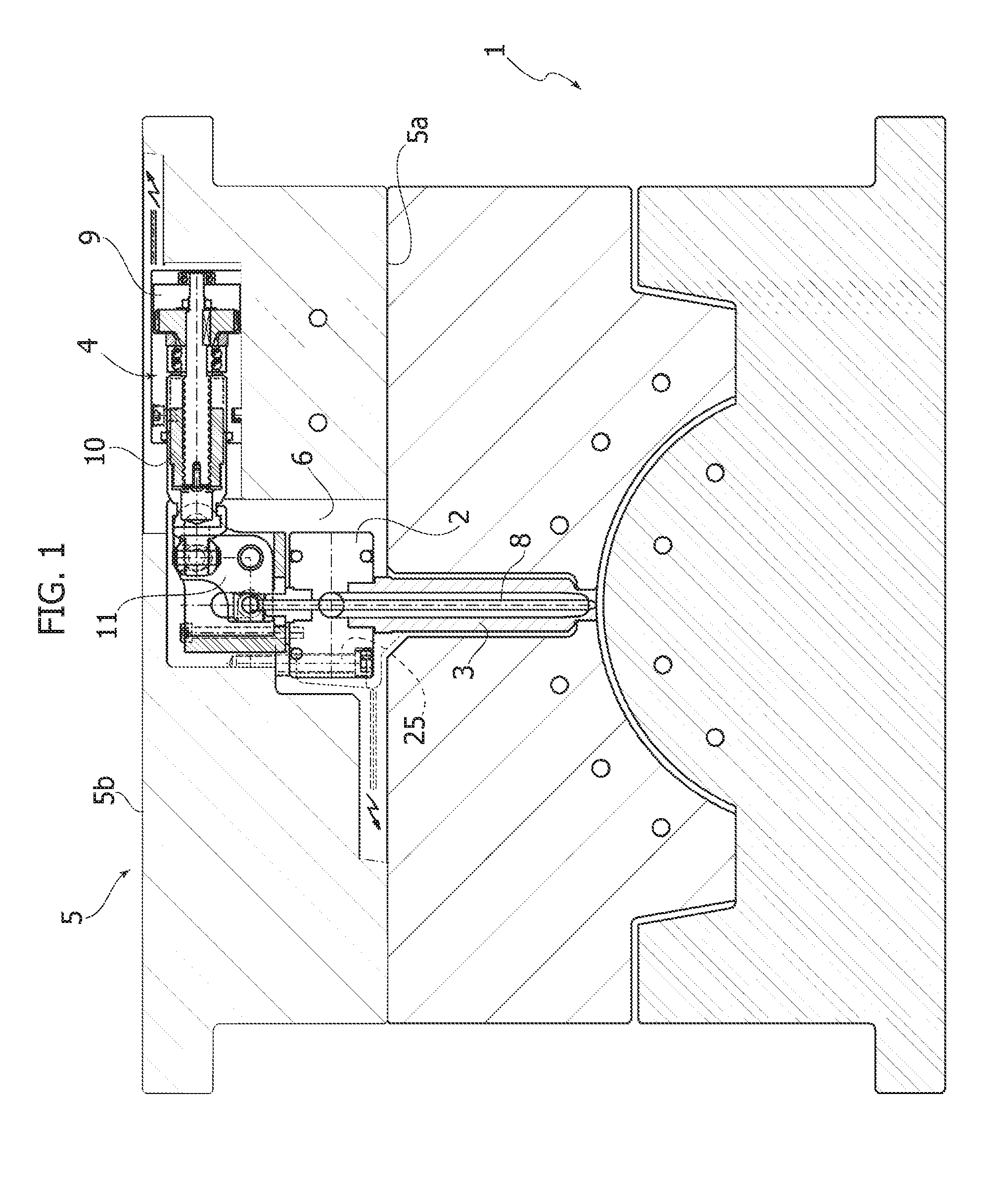
[0036]Referring initially to FIG. 1, the injection molding apparatus according to the invention essentially comprises a mold generically indicated with 1, a distributor or hot chamber 2, filling injectors 3 the introduction of the fluid plastic material under pressure from the distributor 2 to the mold cavity 1, and an actuator device indicated generically with 4 for the operation of each injector 3.

[0037]Numeral 5 indicates a fixing plate or clamping plate configured, possibly in combination with additional plates, for fixing, in the manner known per se, of the mold 1 to the planes of the press of the injection apparatus. The term fixing plate should therefore not be considered in a limiting sense, but is specifically intended to designate any plate interposed between the mold 1 and the planes of the press.

[0038]Referring now to FIGS. 2, 3 and 4, the fixing plate 5 according to the invention, compared with the state of art, has an appreciably reduced thickness and a greater constru...


PUM

PropertyMeasurementUnit
mold temperaturesaaaaaaaaaa
pressureaaaaaaaaaa
thermal expansionaaaaaaaaaa

Abstract

An injection molding apparatus of plastic material including a mold, a fixing plate of the mold, a distributor of the plastic material to be injected and a plurality of injectors connected to the distributor and each including a valve pin controlled by a respective rotary electric motor and a transmission. The fixing plate has a cavity facing the mold on a first face, within which the distributor is contained, and each electric motor with the relative transmission is housed, in a quickly insertable and removable manner, within a respective seat arranged on a second face of the fixing plate opposite to the first face, laterally with respect to the corresponding injector.

Description

CROSS REFERENCE TO RELATED APPLICATIONS[0001]This application claims priority to Italian Patent Application No. TO2014A000188 filed on Mar. 10, 2014, the entire disclosure of which is incorporated herein by reference.FIELD OF THE INVENTION[0002]The present invention relates in general to apparatuses for injection molding of plastic material of the type comprising a mold, a fixing plate of the mold, a distributor of the plastic material to be injected, and a series of injectors connected to the distributor to inject the plastic material into the mold cavity.[0003]In the molding apparatuses of the so-called obturator type, each injector comprises a nozzle connected to the distributor, and within which a valve pin is axially movable, operated by a motor that controls its movement between a closed position and an open position, to allow the flow of fluid plastic material under pressure from the distributor to the mold cavity.[0004]Particularly, the invention relates to the fixing plate ...

Claims


Application Information

Patent Timeline
Patent Type & Authority Patents(United States)
IPC IPC(8): B29C45/23B29C45/70B29C45/28B29L31/00
CPCB29C45/70B29C45/281B29C45/2806B29C2045/282B29C2045/2824B29C2045/2834B29L2031/772B29C45/06B29C2045/1792B29C2045/2817B29C45/2602
Inventor BAZZO, MAURIZIOTREVISIOL, NICO
Owner INGLASS SPA
Features
  • R&D
  • Intellectual Property
  • Life Sciences
  • Materials
  • Tech Scout
  • Unparalleled Data Quality
  • Higher Quality Content
  • 60% Fewer Hallucinations
Learn More