

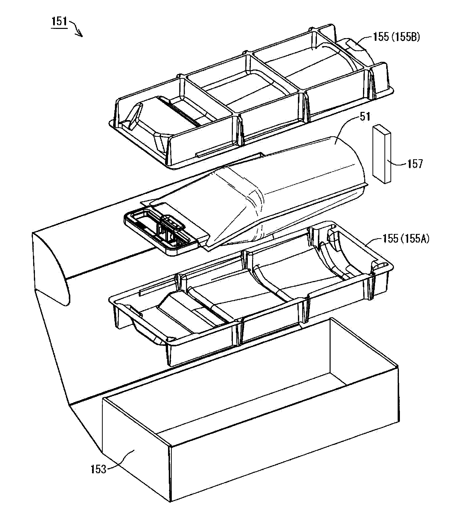
Packaging tray and packaging body
a packaging body and tray technology, applied in printing and other directions, to achieve the effect of convenient protection
- Summary
- Abstract
- Description
- Claims
- Application Information
AI Technical Summary
Benefits of technology
Problems solved by technology
Method used
Image

Examples
Embodiment Construction
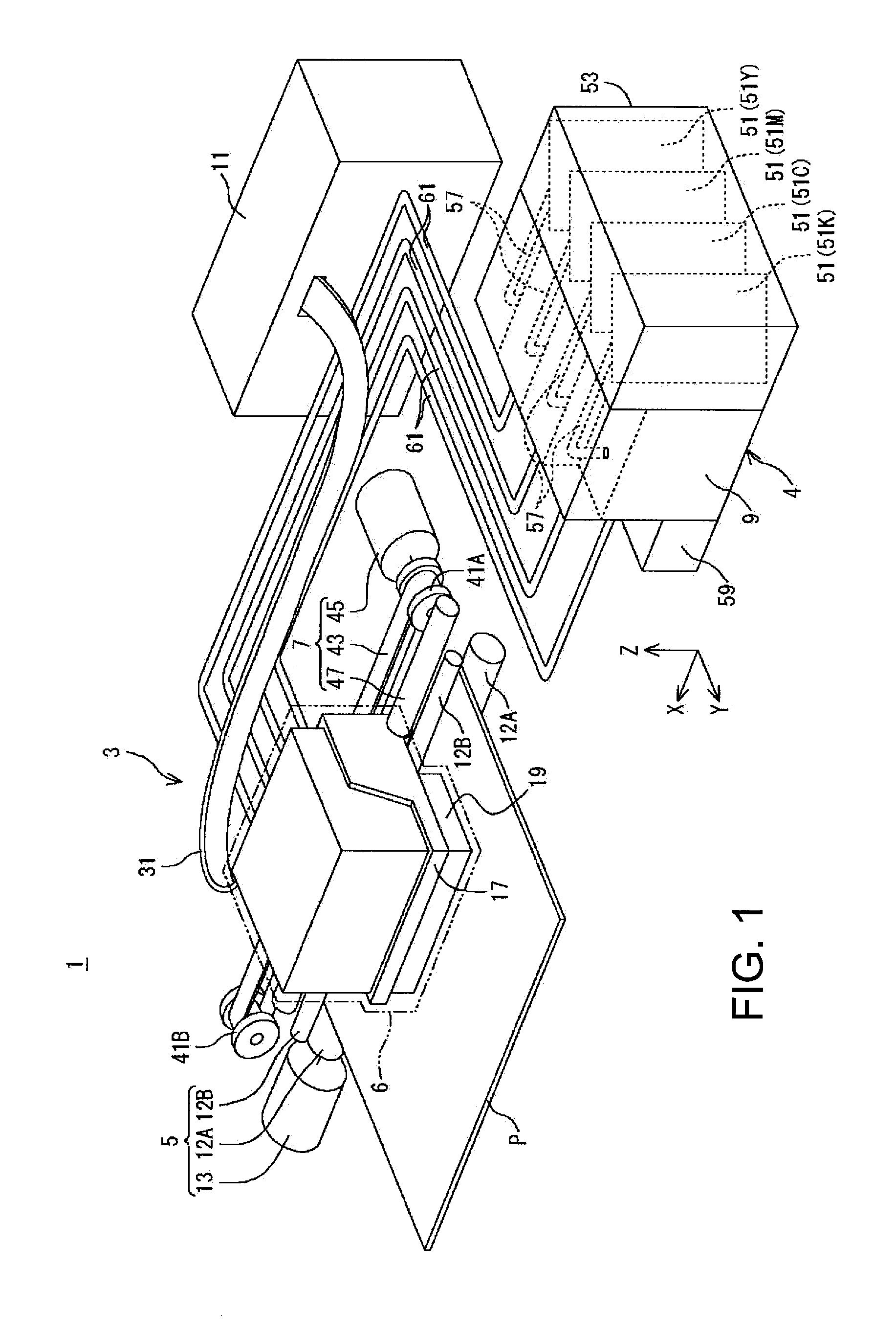
[0058]The following describes an embodiment of the invention with reference to the drawings, taking a liquid ejection system as an example. In the drawings, in order to show individual components in recognizable sizes, the components and members may be shown on different scales.
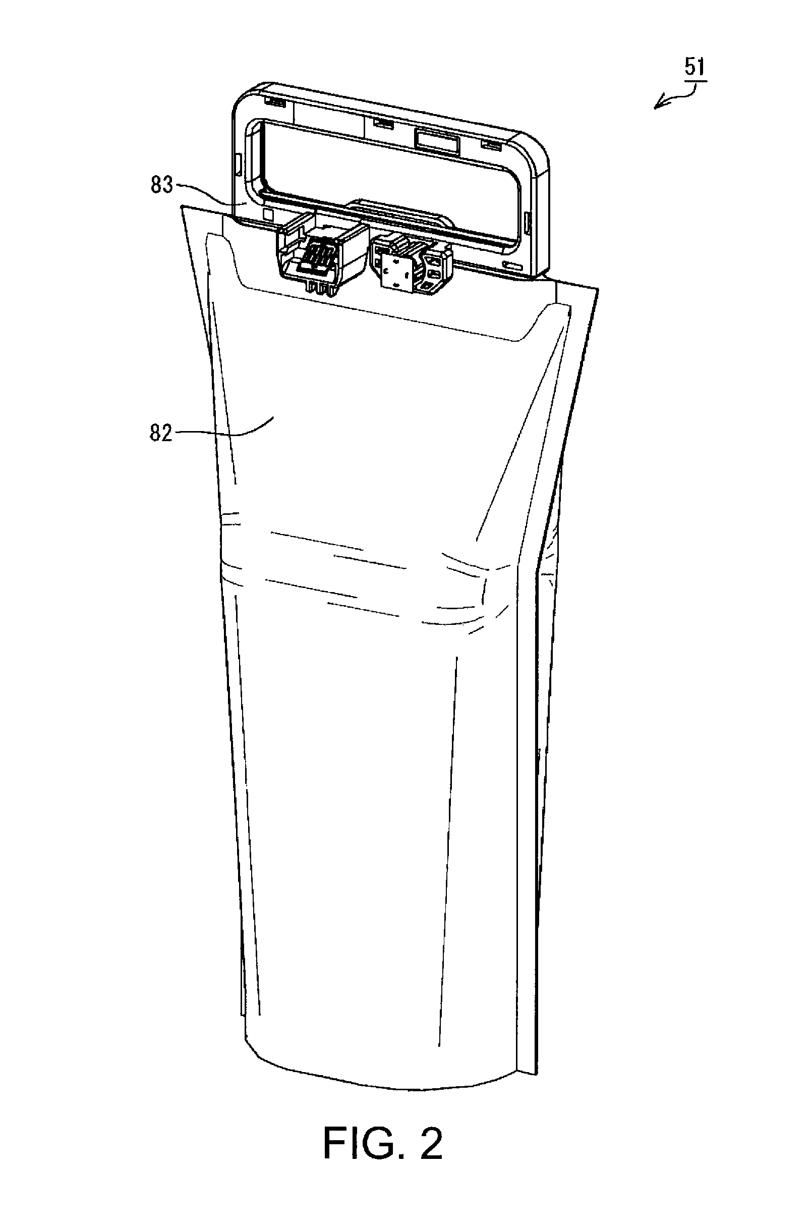
[0059]A liquid ejection system 1 according to the present embodiment has, as shown in FIG. 1, a printer 3, which is an example of a liquid ejection apparatus, and an ink supply apparatus 4, which is an example of a liquid supply apparatus. The printer 3 has a conveyance device 5, a recording unit 6, a moving device 7, a relay device 9, and a control unit 11. It should be noted that in FIG. 1, X-, Y-, and Z-axes, which are coordinate axes that are orthogonal to one another, are shown. The X-, Y-, and Z-axes may also be shown in the drawings described below as necessary. In the present embodiment, a state in which the liquid ejection system 1 is disposed in a horizontal plane (XY plane) defined by the X-axis an...
PUM
 Abstract
Description
Claims
Application Information