
Ejection head for ejecting alignment film forming composition

a technology of alignment film and composition, which is applied in the field of liquid crystal display technology, can solve the problems of affecting easy to form problems, and achieve the effect of avoiding large droplets and greatly enhancing the quality of alignment film

Active Publication Date: 2016-05-24
TCL CHINA STAR OPTOELECTRONICS TECH CO LTD
View PDF18 Cites 0 Cited by
  • Summary
  • Abstract
  • Description
  • Claims
  • Application Information

AI Technical Summary

Benefits of technology

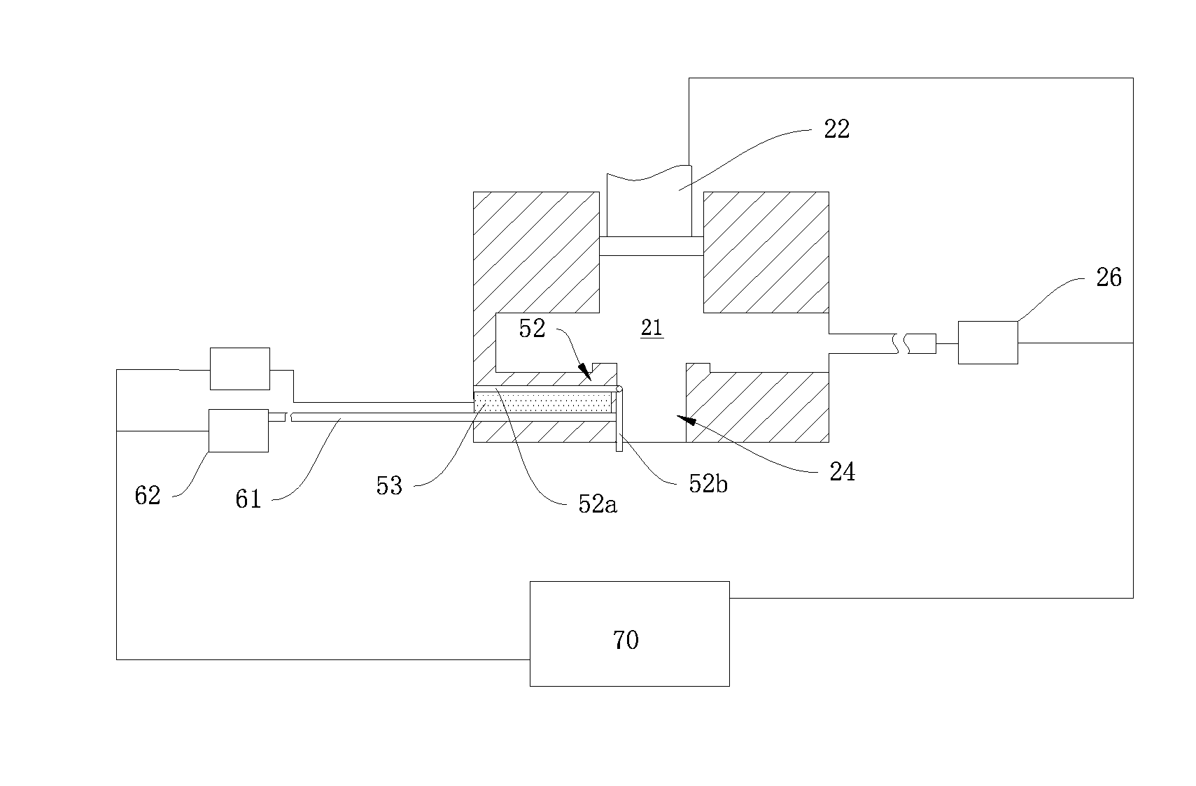
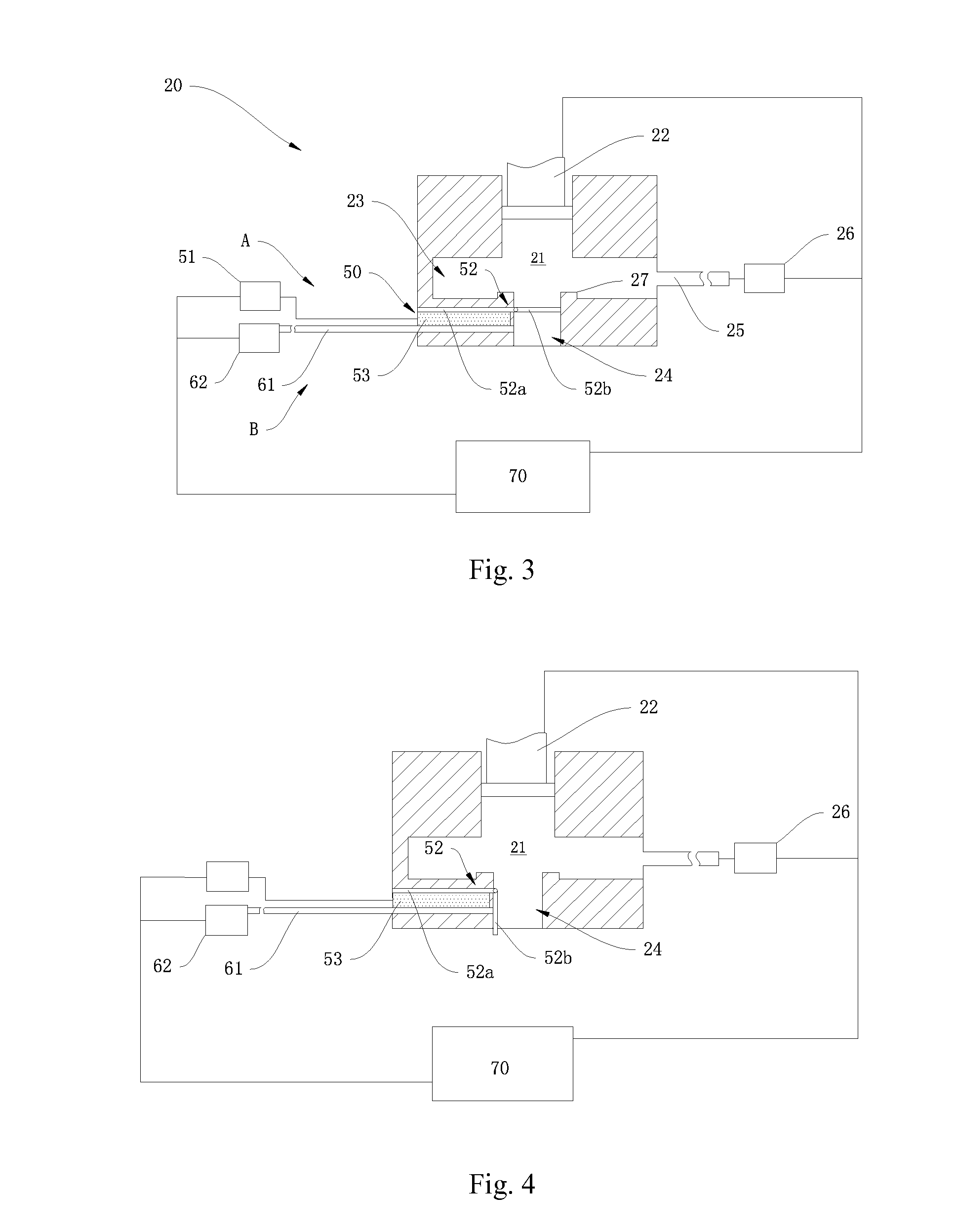
[0015]An object of the present invention is to provide an ejection head for ejecting alignment film forming composition. The ejection head can control flowing timing of the alignment film forming composition properly. The ejection head opens or closes the liquid transportation pipe in a timely way according to a real condition. The ejection head for ejecting alignment film forming composition comprises a plurality of nozzles disposed on a bottom of the ejection head. Each nozzle comprises: a chamber, comprising a liquid transportation pipe and a pusher disposed on a bottom and a top of the chamber, respectively, the liquid transportation pipe and the pusher corresponding with each other, and the pusher used for pushing the alignment film forming composition out of the liquid transportation pipe; a composition source connected to a liquid supply pipe disposed on the chamber, for transporting the alignment film forming composition to the chamber; and a control valve disposed on the liquid transportation pipe, for controlling switching of the liquid transportation pipe for restricting output of the alignment film forming composition.
[0024]In contrast to prior art, a control valve and a blowing device are newly added in the present invention. The control valve is used to control switching of the liquid transportation pipe, which controls the output timing of the alignment film forming composition. In addition, the blowing device is used to keep airflow moving at an exit of the nozzle of the liquid transportation pipe in an idle state, which ensures that the exit of the nozzle is unblocked and that the alignment film forming composition does not aggregate or condense, which prevents the nozzle from being blocked and avoids forming large droplets. In this way, the quality of the alignment film is greatly enhanced owing to uniform spraying and regular output.

Problems solved by technology

Some problems easily occur.
This will affect the quality of the alignment film.
If the large droplets are not sprayed out for a long time, the condensed high polymers will even block the exit of the nozzle, causing the alignment film forming composition to not flow out normally.

Method used


Image

  • Ejection head for ejecting alignment film forming composition
  • Ejection head for ejecting alignment film forming composition
  • Ejection head for ejecting alignment film forming composition

Examples


Embodiment Construction

[0029]The accompanying drawings are included to provide a further understanding of the invention, and are incorporated in and constitute a part of this specification. The drawings illustrate embodiments of the invention and, together with the description, serve to explain the principles of the invention.

[0030]An object of the present invention is to solve problems caused by the conventional nozzle, such as occlusion and drop condensation.

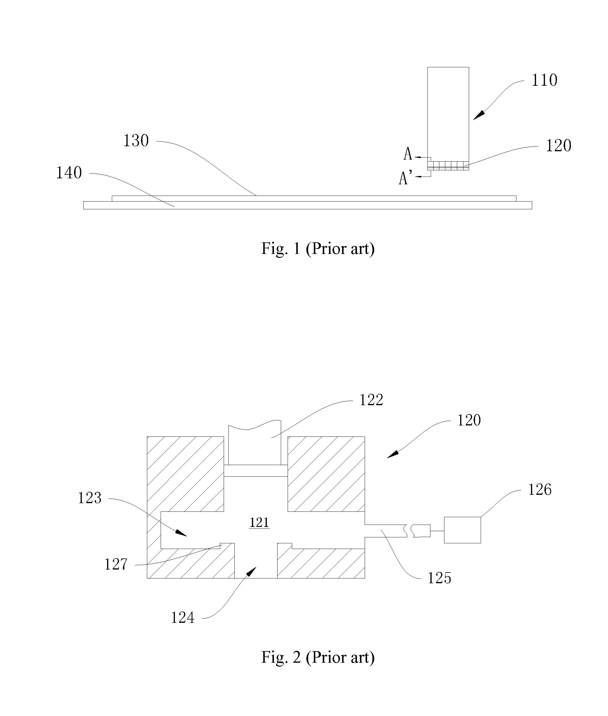
[0031]The ejection head in the present embodiment comprises a plurality of nozzles 20. The structure of the nozzle 20 is improved. FIG. 3 shows the internal structure of the nozzle 20. Each of the plurality of nozzles 20 comprises a chamber 21 and a composition source 26.

[0032]A liquid transportation pipe 24 and a pusher 22 are disposed on the bottom of the chamber 21 and the top of the chamber 21, respectively. The liquid transportation pipe 24 and the pusher 22 correspond with each other. The pusher 22 is used to push the alignment film forming co...


PUM

PropertyMeasurementUnit
angleaaaaaaaaaa
angleaaaaaaaaaa
magnetic forcesaaaaaaaaaa

Abstract

An ejection head for ejecting alignment film forming composition includes multiple nozzles. Each nozzle includes a chamber, a composition source, and a control valve. A liquid transportation pipe and a pusher are disposed on the bottom and the top of the chamber, respectively. The pusher is used for pushing the alignment film forming composition out of the liquid transportation pipe. The composition source is used for transporting the alignment film forming composition to the chamber. The control valve is used for controlling switching of the liquid transportation pipe to control output of the alignment film forming composition. Owing to the control valve and the blowing device, the alignment film forming composition is prevented from condensing on the nozzle and blocking the nozzle or from forming large droplets because of accumulation. In this way, the quality of the alignment film is greatly enhanced owing to uniform spraying and regular output.

Description

BACKGROUND OF THE INVENTION[0001]1. Field of the Invention[0002]The present invention relates to a liquid crystal display technology, and more particularly, to the improvement of an ejection head for ejecting alignment film forming composition.[0003]2. Description of the Prior Art[0004]A liquid crystal display (LCD) includes two glass substrates and a liquid crystal layer disposed between the glass substrates. At present, the LCD mainly refers to a thin film transistor (TFT) LCD. Basically, it takes three processes to produce the TFT LCD: to form patterns on the glass substrates, to seal liquid crystal between the glass substrates to form a liquid crystal cell, and to assemble a liquid crystal module (LCM). To cost down and to make products diverse, more than one liquid crystal cell is used on the glass substrates; instead, multiple liquid crystal cells are horizontally arranged on the glass substrates. The number of the liquid crystal cells and the position of the liquid crystal ce...

Claims


Application Information

Patent Timeline
Patent Type & Authority Patents(United States)
IPC IPC(8): G02F1/13B05B15/02B05B1/30B05B1/14G02F1/1337B05B15/55
CPCG02F1/1303B05B1/3053B05B15/025B05B1/14G02F1/1337B05B15/55
Inventor LIU, MINGSONG, TAOMA, TAOZHAO, GUODONG
Owner TCL CHINA STAR OPTOELECTRONICS TECH CO LTD
Learn More