Abdominal aortic tourniquet

Active Publication Date: 2016-05-31
TREBOR IND
View PDF1 Cites 3 Cited by
  • Summary
  • Abstract
  • Description
  • Claims
  • Application Information

AI Technical Summary

Benefits of technology

The present invention is a novel abdominal aortic tournicket with a triangular or triangular cross-section shape that corrects the problem of prior art designs by providing the appropriate amount of point pressure to occlude the artery. The design is one-piece and has a significantly increased amount of point pressure compared to prior designs, resulting in the proper occluding of the artery. This design also reduces the cost of materials and makes the piece more compact.

Problems solved by technology

This prior art design requires a separate gas holding inner bladder and outer shell cover, and despite its objectives is also known to not provide for sufficient point pressure required to occlude an artery.

Method used


Image

  • Abdominal aortic tourniquet
  • Abdominal aortic tourniquet
  • Abdominal aortic tourniquet

Examples


first embodiment

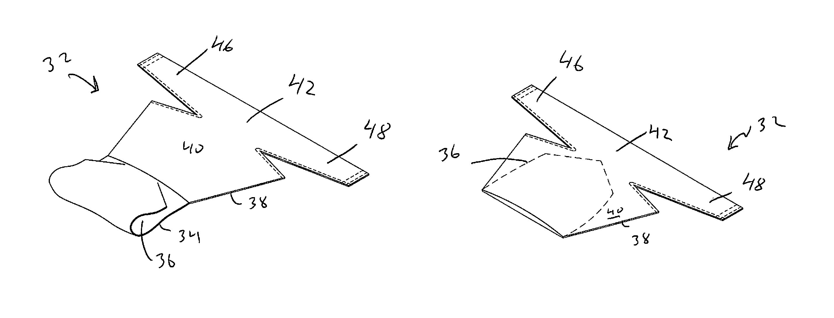
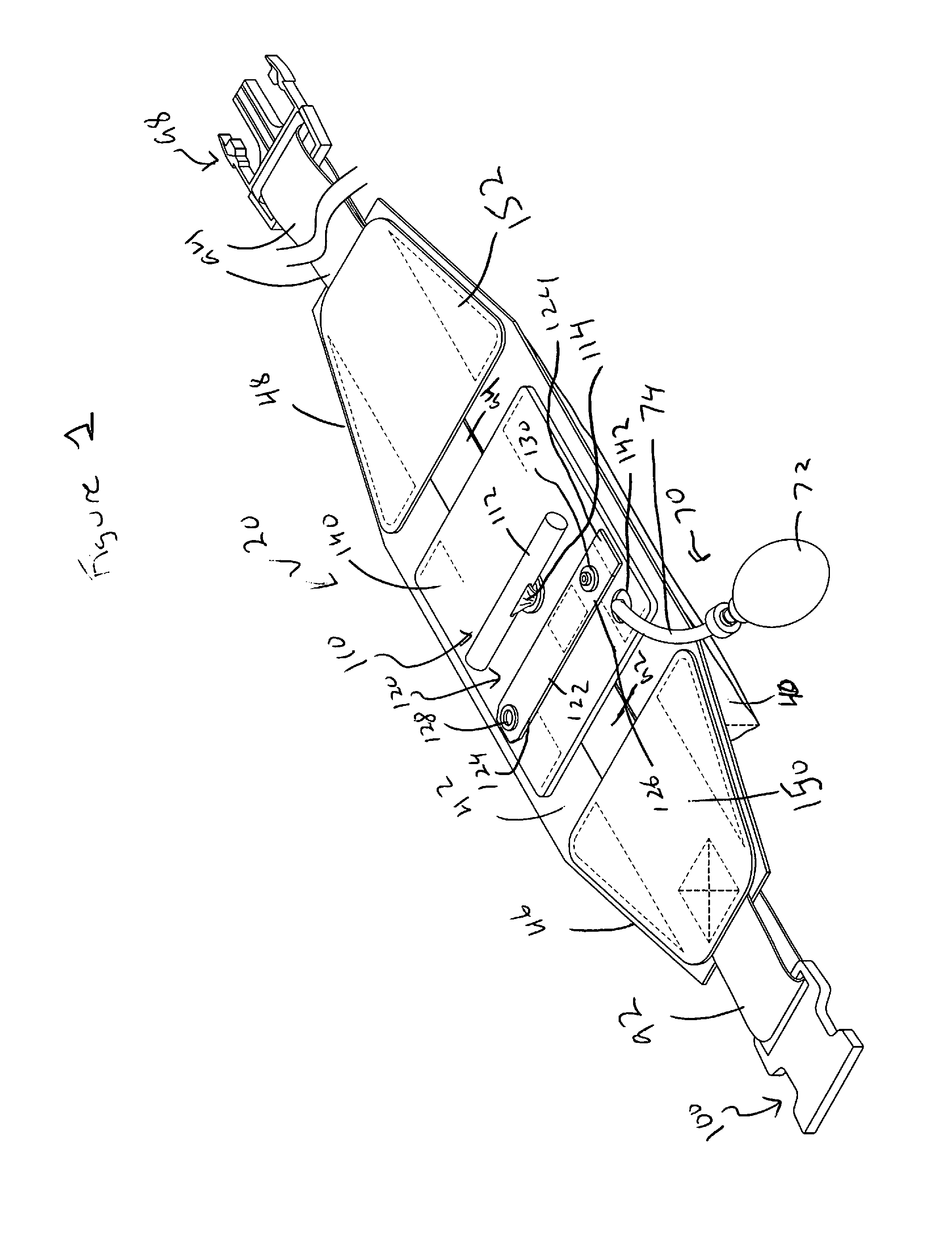
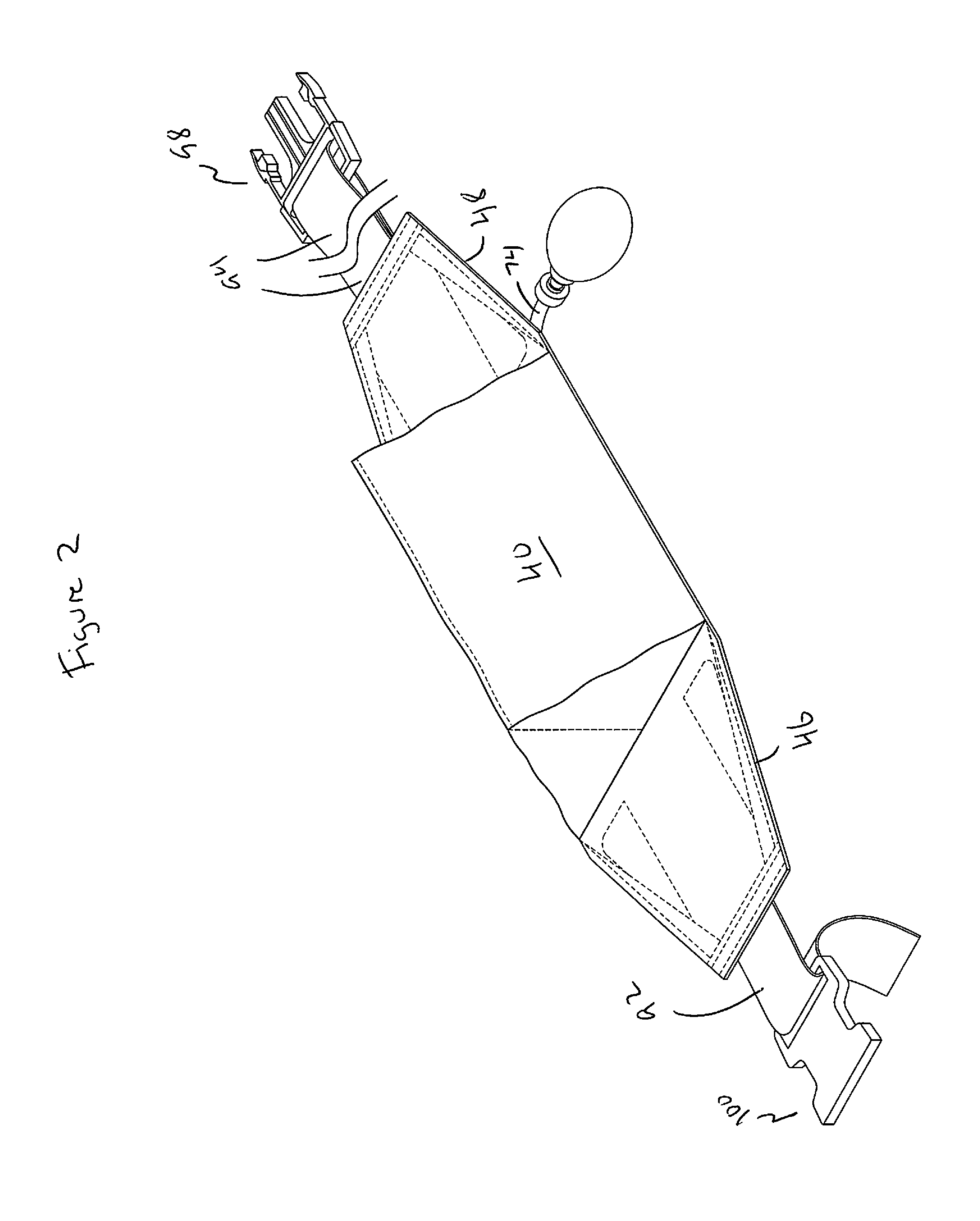
[0032]As seen in FIGS. 1 through 8, a first embodiment for an abdominal aortic tourniquet is shown with tourniquet generally designated as reference number 20. As best seen in FIGS. 5-7, tourniquet 20 can comprise a monolithically formed one-piece member 32 having a first sealed section 34 to form a bladder 36, a second section 38 forming a receiving pocket 40 and a top section 42. Bladder 36 is formed from welding portions of first sections 34 together though such is not considered limiting and other known methods for creating a sealed bladder can also be used and are considered within the scope of the invention. As seen in FIG. 5, when one-piece member 32 is in a flat or unfolded configuration, prior to assembly of tourniquet, second section 38 is positioned above first section 34 and top section 42 is above second section 38. As best seen in FIG. 6, one-piece member 32 is folded at a point between first section 34 and second section 38 such that first section 32, including sealed...

second embodiment

[0050]FIG. 9 illustrates a second embodiment for an abdominal aortic tourniquet of the present invention and is generally illustrated as reference numeral 220. In this embodiment, plates 60, 150 and 152 have been eliminated and fabric sleeves 222 and 224 are secured to wings 46 and 48, respectively, to serve as the belt portion position maintainers. Sleeves 222 and 224 are preferably sewn to wings 46 and 48. However, any conventional methods for securing can be used and are considered within the scope of the invention. Similar fabric loops 232 and 234 are provided for maintaining the position of belt portions 92 and 94 that were maintained by plate 60 in the embodiment shown in FIG. 1. Fabric loops 232 and 234 can also be preferably sewn to top section 42, though other conventional securement methods can also be used and are considered within the scope of the invention. The operation of tourniquet 220 and the remaining parts of tourniquet 220 are similar to those described above for...

third embodiment

[0051]FIG. 10 illustrates a third embodiment for an abdominal aortic tourniquet of the present invention and is generally illustrated as reference numeral 320. In this embodiment, plates 150 and 152 have been eliminated and one or more fabric loops 322 are secured to wings 46 and 48 to serve as the belt portion position maintainers. Loops 322 are preferably sewn to wings 46 and 48. However, any conventional methods for securing can be used and are considered within the scope of the invention. The operation of tourniquet 320 and the remaining parts of tourniquet 320 are similar to those described above for the tourniquet embodiment of FIG. 1.


PUM


Abstract

An abdominal aortic tourniquet having one-piece member for the bladder and cover portions and whose bladder has a triangular cross-sectional shape when inflated that significantly increases the amount of point pressure such that the intended artery is properly occluded. The one-piece bladder / cover design provides for a reduction in cost of materials and provides for a more compact piece as compared to prior designs. The abdominal aortic tourniquet uses a single piece of weldable and gas impermeable fabric that is configured in a novel manner to create a three-dimensional, pneumatic piston while also serving as storage / transport cover, attachment structure, and major component of the belt member.

Description

[0001]This application claims the benefit of and priority to U.S. Provisional Patent Application Ser. No. 61 / 719,194, filed Oct. 26, 2012, which is incorporated by reference in its entirety.1. FIELD OF THE INVENTION[0002]The present invention is directed to an abdominal aortic tourniquet which is an improvement over previous abdominal aortic tourniquets.2. BACKGROUND OF THE INVENTION[0003]A prior art design for an abdominal aortic tourniquet can be seen in published pending application Ser. No. 12 / 150,728 listed John Croushorn as inventor (“the '728 application”), the '728 application is incorporated by reference in its entirety particularly for its discussion on using an abdominal aortic tourniquet for occluding blood flow. The prior art design is intended to occlude the descending aorta at the bifurcation into the left and right iliac arteries. The prior art design is a non-invasive device intended for cross-clamp of the descending aorta. The primary use for the prior art design i...

Claims


Application Information

Patent Timeline
IPC IPC(8): A61B17/135
CPCA61B17/135A61B17/1322
Inventor CARMICHAEL, ROBERT MANUELMORRIS, JEFFGRASSO, STEPHEN
Owner TREBOR IND
Why Eureka
Try Eureka