Rheometry apparatus

a technology of rheometry and apparatus, which is applied in the direction of direct flow property measurement, manufacturing tools, instruments, etc., can solve the problems of reducing the accuracy of pressure measurements obtained on the sample, difficult and/or expensive production of apparatus, etc., and achieves the effect of convenient arrangemen

Inactive Publication Date: 2016-05-31
UNIV OF MANCHESTER
View PDF13 Cites 0 Cited by
  • Summary
  • Abstract
  • Description
  • Claims
  • Application Information

AI Technical Summary

Benefits of technology

[0005]Certain embodiments aim to provide rheometry apparatus for large scale high-throughput rheological measurements. Certain embodiments aim to provide rheometry apparatus for dynamic measurements under oscillatory flow. Certain embodiments aim to provide rheometry apparatus that is simpler and cheaper to produce than previous arrangements. Certain embodiments aim to provide apparatus for use in rheometry which provides the user with flexibility in terms of the type and position of sensors to be used to measure characteristics of samples flowing in one or more flow channels. Certain embodiments aim to provide rheometry apparatus which can be used to obtain flow measurements from samples of liquids having very small volumes (i.e. 100 microliters and even smaller).
[0058]Advantageously, arranging a sensor inside a sealed volume or side chamber, separated from the flow channel by a constriction, such as a small diameter mouth, a property of fluid flow within the channel can be accurately measured without disturbing flow and without requiring expensive and inflexible integration of a sensor or sensors within the first or second bodies during manufacture.

Problems solved by technology

Although such apparatus is of use, it will be appreciated that disadvantages associated with the integrated pressure sensor arrangement are that the apparatus may be difficult and / or expensive to produce, once the arrangement has been manufactured there is no flexibility in where to locate the pressure sensors, and the separation of the pressure sensors from the flowing liquid by even a small thickness of material can reduce the accuracy of the pressure measurements obtained on the sample.

Method used


Image

  • Rheometry apparatus
  • Rheometry apparatus
  • Rheometry apparatus

Examples


Embodiment Construction

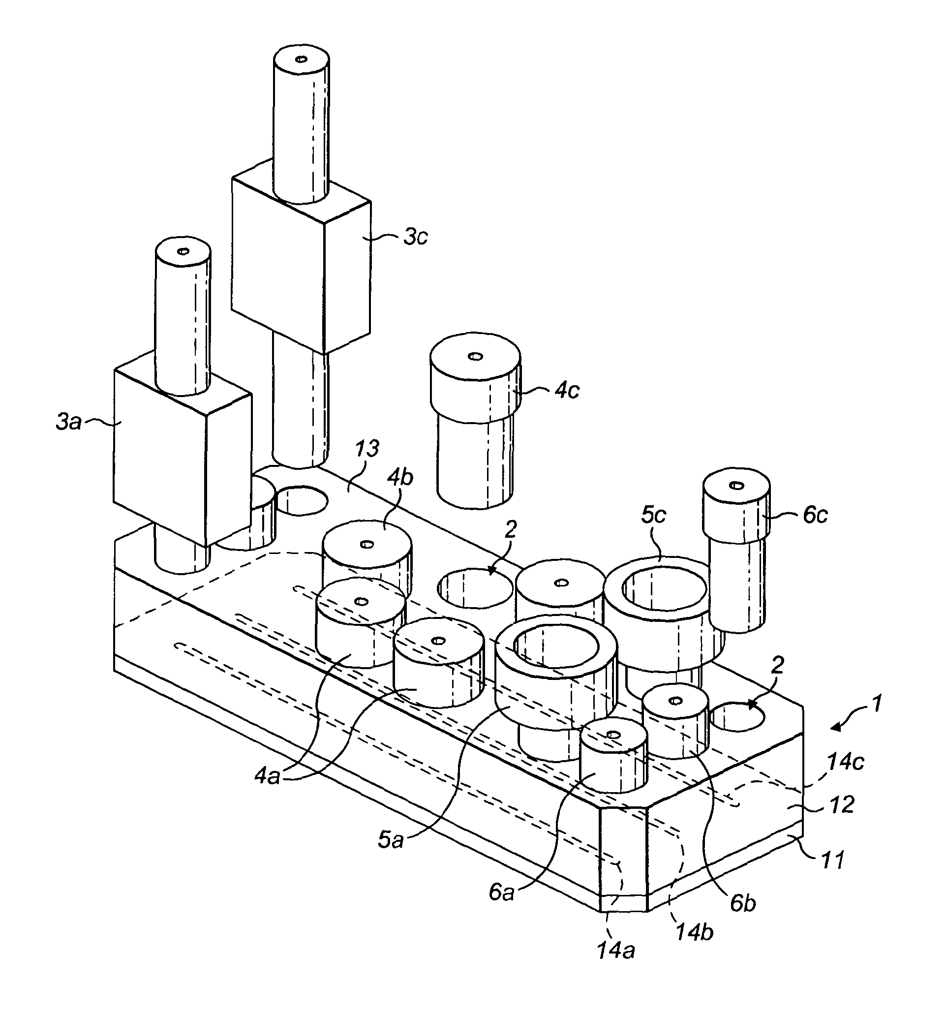
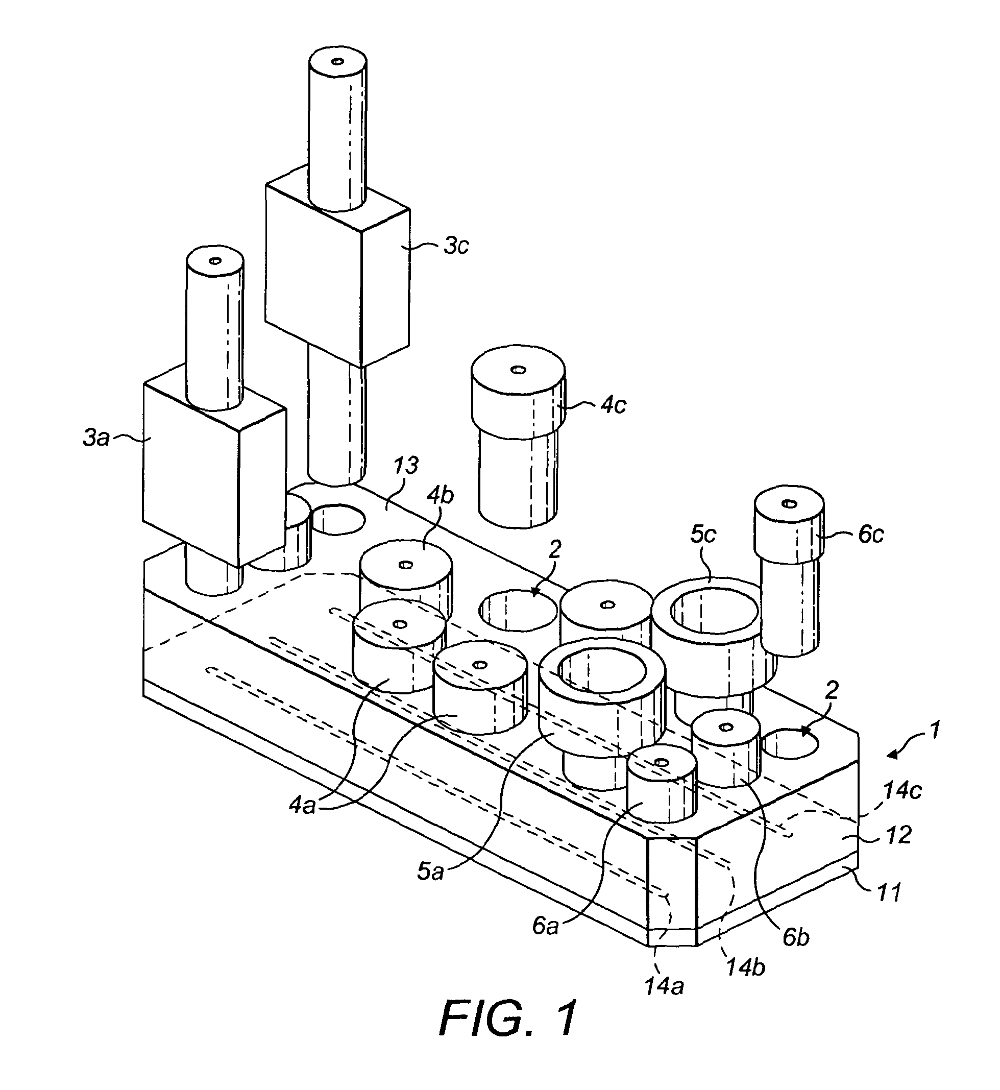
[0077]Referring now to FIG. 1, a rheometer (which may also be described as rheometry apparatus and / or a rheometry system) embodying the present invention comprises a block 1 of substantially rigid and transparent material formed by attaching a first block portion 11 to a second block portion 12. The assembled block 1 comprises three separate and co-planar micro flow channels 14a, 14b, and 14c. These three flow channels are defined at the interface between flat mating surfaces of the first block portion 11 and second block portion 12. The block 1 also comprises a plurality of access holes 2, each of which is arranged to communicate with one of the internal flow channels at a respective position along that channel's length and to extend from that position upwards to a substantially flat external surface 13 of the block 1. Thus, each hole or aperture 2 provides access to one of the internal flow channels so that pumping means, sensors etc can be attached to the block 1 and generate a m...


PUM

PropertyMeasurementUnit
volumeaaaaaaaaaa
volumesaaaaaaaaaa
volumeaaaaaaaaaa

Abstract

Rheometry apparatus comprises a block of substantially rigid material having an external surface and at least a first internal flow channel, the first internal flow channel being arranged inside the block and substantially in a plane and the block further comprising a plurality of holes, each hole communicating with the first internal flow channel at a respective position along the first internal flow channel and extending from the respective position to said external surface so as to provide access to the first internal flow channel from the external surface, the plurality of holes comprising a first hole communicating with a first said position, for connection to pumping means to drive fluid flow along said first internal flow channel, a second hole communicating with a second position and in which a sensor may be located to measure a property of fluid at the second position, and a third hole communicating with a third position and in which a sensor may be located to measure a property of fluid at the third position.

Description

RELATED APPLICATIONS[0001]This application is a §371 of International Patent Application No. PCT / GB2011 / 051476 filed Aug. 3, 2011, which claims priority to Great Britain Patent Application No. 1013044.1, which was filed Aug. 3, 2010, all of which are incorporated by reference herein.FIELD OF THE INVENTION[0002]The present invention relates to rheometry apparatus, that is apparatus for rheological characterisation of a sample liquid. Certain embodiments are concerned in particular, although not exclusively, with micro-rheometers and apparatus for large scale high-throughput rheological characterisation of fluid samples using only very small volumes of complex fluids such as polymer solutions, DNA and protein solutions, synovial fluids, bloods, and other cellular solutions.BACKGROUND TO THE INVENTION[0003]A variety of rheometers are known for measuring rheological properties such as viscosity and elasticity of sample liquids. For example, US 2008 / 0134765 A1 discloses a micro-rheometer...

Claims


Application Information

Patent Timeline
Patent Type & Authority Patents(United States)
IPC IPC(8): G01N11/08
CPCG01N11/08Y10T29/49826
Inventor YUAN, XUE-FENG
Owner UNIV OF MANCHESTER
Why Eureka
Try Eureka