Telescopic tube for electric household appliances equipped with electricity conduction means

a technology of electric household appliances and telescopic tubes, which is applied in the direction of screw thread joints, mechanical equipment, cleaning equipment, etc., can solve the problems of unsuitable for use in electric household appliances, unfavorable domestic accidents, and excessively large dimensions of telescopic tubes, so as to reduce the risk of short-circuits and domestic accidents, the effect of simple and cheaper production

Inactive Publication Date: 2011-02-08
OMEC SPA
View PDF27 Cites 12 Cited by
  • Summary
  • Abstract
  • Description
  • Claims
  • Application Information

AI Technical Summary

Benefits of technology

[0019]In particular, a first object of the technology disclosed herein is to provide a telescopic tube of the abovementioned type which is light and manageable and therefore suitable for use in electric household appliances such as a vacuum cleaner or the like.
[0020]A further object of the technology disclosed herein is to provide a telescopic tube of the abovementioned type in which the electricity conduction means are more resistant to wear than those present in the known tubes and in which in general the risk of short-circuits and domestic accidents is reduced.
[0021]A further object of the technology disclosed herein is to provide a telescopic tube of the abovementioned type which is simpler and cheaper to produce than the known tubes.

Problems solved by technology

The solution of DE 195 35 493 involves certain disadvantages: the presence of the pulley system inside the cabling duct results in excessively large dimensions of the said duct and consequently the electrified telescopic tube.
For this reason, this type of tube is not very easy to handle and therefore unsuitable for use in electric household appliances.
Moreover, so that the cable may be housed inside the cabling duct and wound around the pulley, it must be bent inside the cabling duct; these bent sections result in wear of the cable—in particular its insulating coating—and therefore with time may give rise to dangerous short-circuits.
Moreover this known electrified tube has a complicated structure and requires assembly which is long and costly.
The solution of EP 0.848,926 B1 is also disadvantageous in terms of overall dimensions of the tube: helical winding of the electric cable in fact requires the cabling duct having dimensions such as to prevent excessive bending of the cable, in order to prevent problems of wear thereof which may result in dangerous short-circuits.
In order to reduce the cross-sectional dimension of the outer suction tube, ducts and tubes with an irregularly shaped cross-section are used, these being difficult and costly to produce.
The arrangement according to EP 0 835 632 is disadvantageous as it is not safe, it is rather complicated to be assembled and bulky.
First of all, the electric contact is provided by means of conductors which are substantially linear and which, being arranged parallel to the axis of the tube, occupy a limited amount of space.
Therefore, the risks of wear of the insulating coatings and consequent short-circuits are limited compared to known solutions.

Method used


Image

  • Telescopic tube for electric household appliances equipped with electricity conduction means
  • Telescopic tube for electric household appliances equipped with electricity conduction means
  • Telescopic tube for electric household appliances equipped with electricity conduction means

Examples


Embodiment Construction

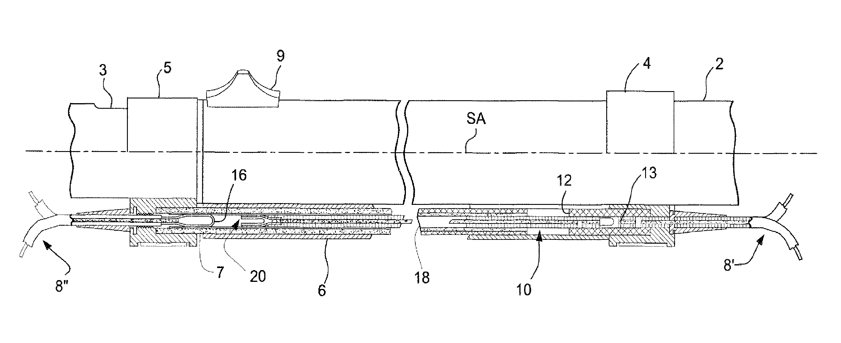
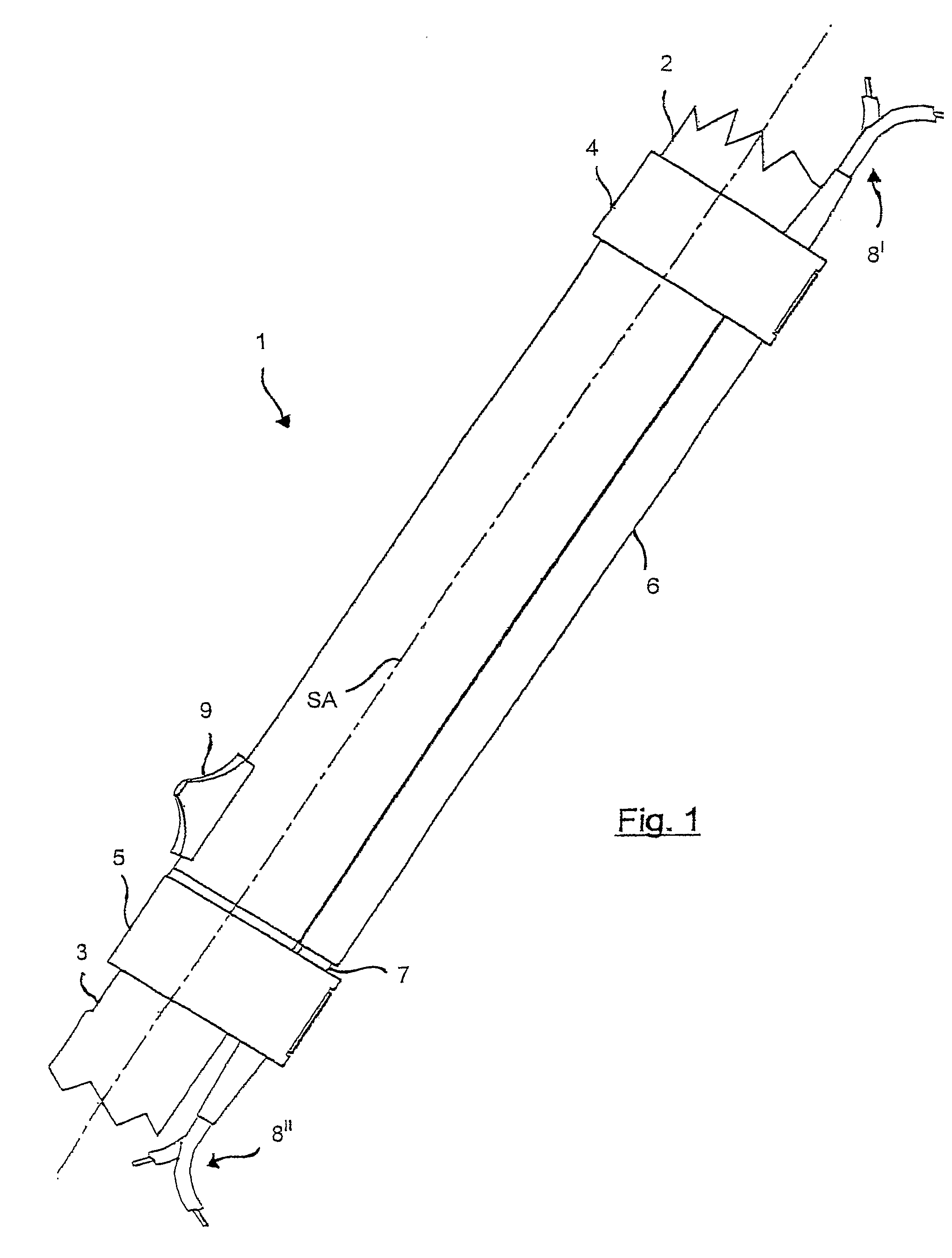
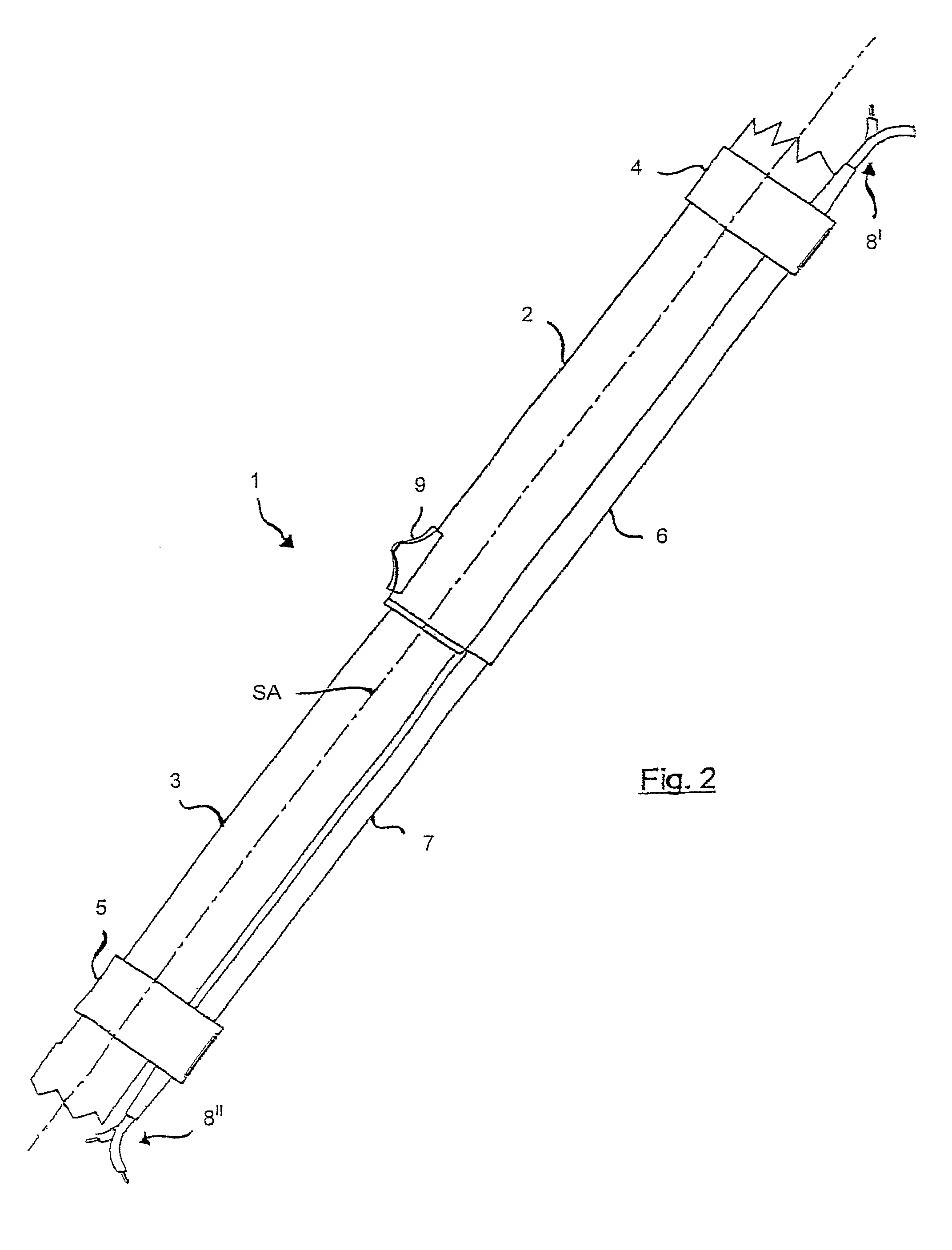
[0059]FIG. 1 and FIG. 2 are axonometric views of the telescopic tube according to the technology disclosed herein, in its closed and extended configuration, respectively. The telescopic tube 1 comprises an outer tube 2, an inner tube 3 sliding inside the outer tube 2, an outer channel 6 fixed to the outer tube 2 and a guide body 7 fixed to the inner tube and sliding inside the outer channel 6. A pushbutton 9 for actuating the telescopic extension mechanism projects from the outer tube. The outer channel 6 and the guide body 7 comprise conductive means which allow electrical conduction along the telescopic tube 1, namely means which provide an electrical contact between two electric power cables 8′ and 8″ from the network and to the motor of an electric household appliance. The conductive means are not shown in FIGS. 1 and 2 but will be described further below with reference to the other figures. FIGS. 1 and 2, on the other hand, show locking collars 4 and 5 which will be described i...


PUM


Abstract

A telescopic tube for an electric household appliance comprises a first outer tube and a second inner tube slidable inside the first outer tube. An eletricity conduction system comprises: a) an elongate guide body comprising non electrically conductive material; b) a locking member for connecting the first end of the elongated guide body to the second inner tube; c) an outer channel connected to an outer surface of the first outer tube, the outer channel being provided for slidingly receiving the elongated guide body; d) a pair of tubular-shaped electric conductors contained in the elongated guide body; and e) a corresponding pair of substantially rigid rod-shaped electric conductors which are able to slide, at least partially, within the tubular-shaped electric conductors so that each rod-shaped electric conductor is in contact with an inner surface of a corresponding tubular-shaped electric conductor.

Description

[0001]This application is the US national phase of international application PCT / EP2005 / 006909 filed 27 Jun. 2005, which designated the U.S. and claims priority to IT MI2004A001429 filed 16 Jul. 2004, the entire content of each of which is hereby incorporated by reference.BACKGROUND[0002]I. Field of the Invention[0003]The present invention relates to a telescopic tube for electric household appliances. In particular, the present invention concerns a telescopic tube for electric household appliances equipped with means for conducting electricity along the said tube.[0004]II. Related Art and Other Considerations[0005]In the sector of electric household appliances such as vacuum cleaners, carpet beaters or the like it is advantageous to use telescopic tubes which increase the versatility thereof. Particularly advantageous are so-called “electrified telescopic tubes”, namely tubes comprising means for conducting electricity along the said tube. These may be used, for example, in a vacuu...

Claims


Application Information

Patent Timeline
Patent Type & Authority Patents(United States)
IPC IPC(8): A47L9/24
CPCA47L9/244A47L9/246Y10S285/907A47L9/24
Inventor CANALE, GIUSEPPE
Owner OMEC SPA
Why Eureka
Try Eureka