
Column tray

a column and trays technology, applied in the field of columns and trays, can solve the problems of inability to produce without considerable cost of corrosion-resistant materials, and less corrosion resistance of ceramics and enamels, etc., to achieve simple production, low cost, and high free cross-section

Inactive Publication Date: 2007-06-26
QVF ENG GMBH
View PDF24 Cites 19 Cited by
  • Summary
  • Abstract
  • Description
  • Claims
  • Application Information

AI Technical Summary

Benefits of technology

[0015]This column tray assembly according to the invention is simpler and cheaper to produce because the formation of a flat tray which can therefore be enamelled is possible by increasing the free cross-section for the gas penetration in the superstructures.
[0039]The tray according to the invention has the advantage that the operator of the column need stock only one universal basic tray as a spare part for all types of column tray assemblies. In addition, the universal tray can be manufactured in relatively large quantities, thus enabling the manufacturing costs to be reduced.

Problems solved by technology

This small free cross-section has the considerable disadvantage that no high gas loads (F factors greater than 1.8) and liquid loads (greater than 40 m3 / m2h) can be run in the column, although this would be possible with modern structured packings and random packings.
However, ceramic has less corrosion resistance than glass and enamel.
Tantalum constructions are considerably more expensive than steel / enamel constructions.
These known column trays have the disadvantage that they cannot be produced without considerable costs for corrosion-resistant materials.

Method used


Image

  • Column tray
  • Column tray
  • Column tray

Examples


Embodiment Construction

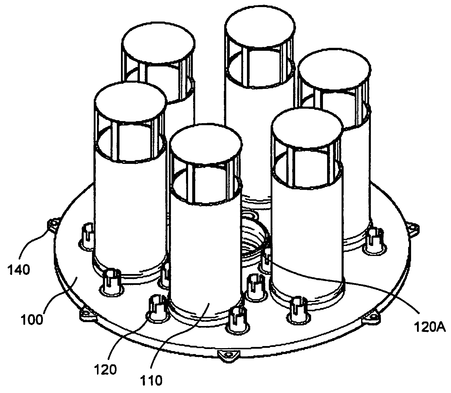
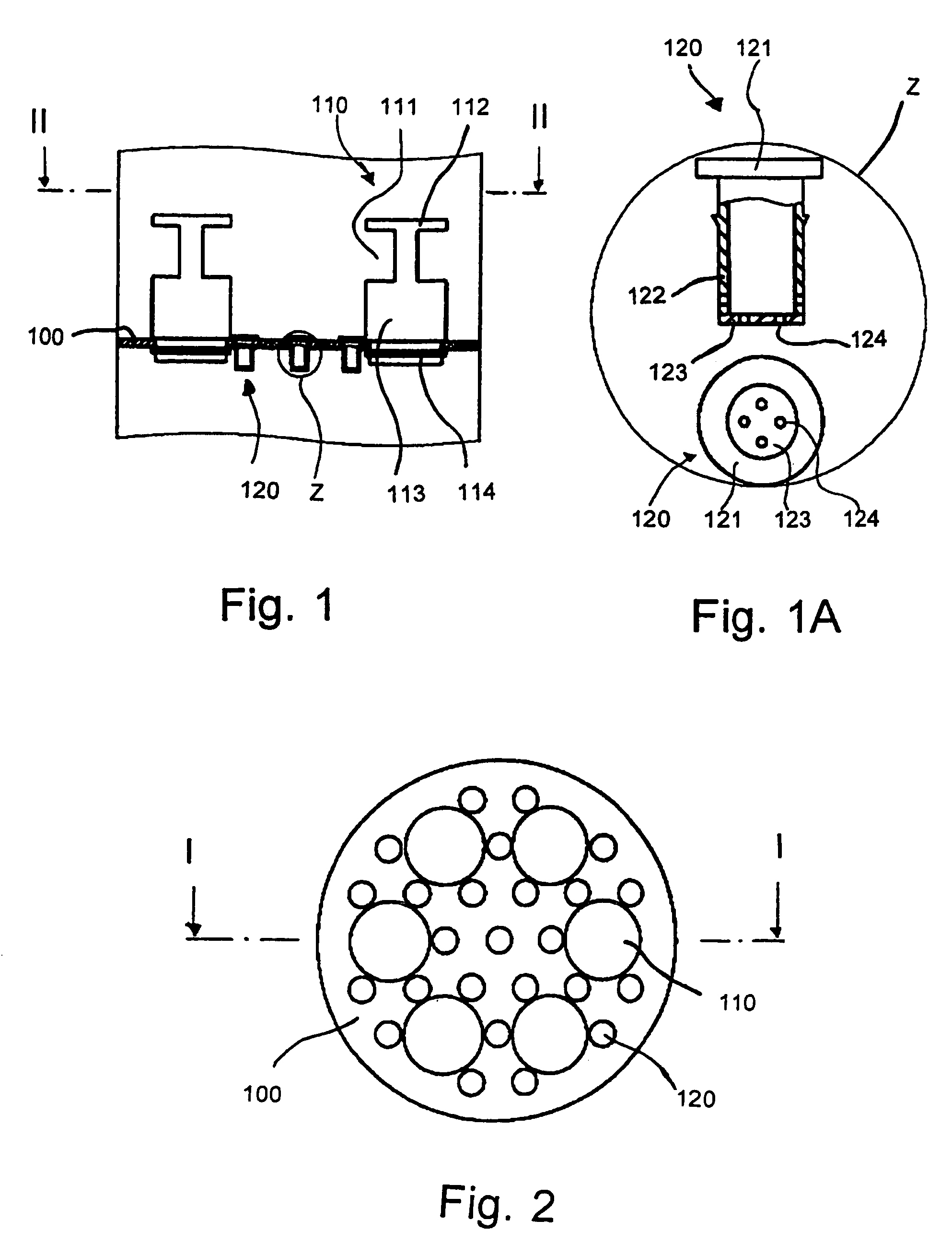
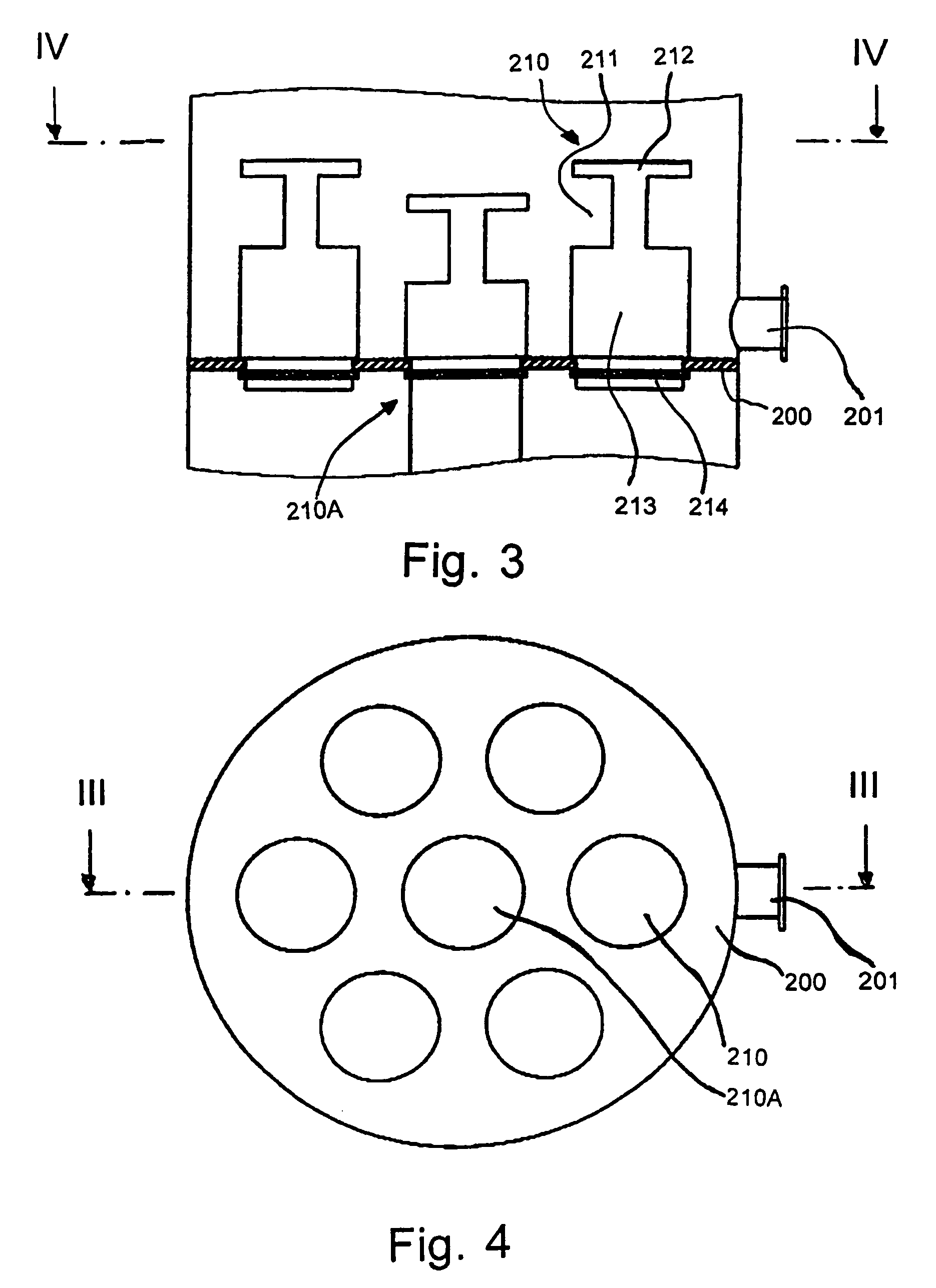
[0064]FIGS. 1 and 2 show column tray assembly according to the invention, which can be used as a liquid distributor and liquid redistributor. FIG. 1 shows a partial cross-section of a column having a liquid distributor or liquid redistributor according to the invention, along the line I-I of FIG. 2. The column tray assembly has a tray 100. This is as a rule mounted in the column by clamping with the aid of flanges (not shown). If the tray 100 includes a metal coated with enamel or plastic, the coating need not necessarily extend up to the clamped borders or up to border edges. Relatively large holes for receiving the superstructures 110 and relatively small holes for receiving distributor cups 120 are formed in the tray. The superstructures 110 substantially comprise a cylinder which is closed at the top with a hood 112 and open at the bottom and in which longitudinal slots are formed above a certain level. In the embodiment shown, two longitudinal slots 111 are formed in the supers...


PUM

PropertyMeasurementUnit
diameteraaaaaaaaaa
diameteraaaaaaaaaa
corrosion-resistantaaaaaaaaaa

Abstract

A column tray assembly includes a tray having passages formed therein. The tray is a multifunction tray and is configured to receiving appropriate superstructures which can be selected according to the respective use of the assembly. Superstructures which communicate with the passages are mounted to the tray. The superstructures have gas penetration holes embedded in such way that, when the superstructures are mounted to the tray, the orifices of the gas penetration holes extend in a perpendicular manner in relation to the tray. The tray and the superstructures are formed from the same or different corrosion-resistant materials or combination of materials. The tray may also be provided with smaller holes for the discharge of liquid, into which holes distributor cups, or the like are inserted. These smaller holes may be closed for specific purposes.

Description

RELATED APPLICATIONS[0001]This is a Continuation-in-Part of International Application No. PCT / EP02 / 09253 filed Aug. 19, 2002, which designated the United States, published as WO 03 / 015889, and whose contents are incorporated by reference.FIELD OF THE INVENTION[0002]The present invention relates to column trays and columns including such column trays.BACKGROUND OF THE INVENTION[0003]In the case of known columns comprising structured packings and / or random packings, these are held in the column by at least one support tray. The liquid is distributed as uniformly as possible over the bed of structured packings or bed of random packings at the feed point or the reflux point by means of a liquid distributor tray. The structured packings or the random packings rest on the support tray. The column has, as a rule, a plurality of beds of structured packings or random packings. Between two successive beds of structured packings or random packings, the liquid must be distributed as uniformly a...

Claims


Application Information

Patent Timeline
Patent Type & Authority Patents(United States)
IPC IPC(8): B01F3/04B01D3/26B01D3/00B01D3/20B01D3/22B01J19/30B01J19/32
CPCB01D3/008B01D3/20B01D3/22B01J19/305B01J19/325B01J2219/192B01J2219/1923B01J2219/194
Inventor DICHTL, GOTTFRIEDWALTER, ULRICH
Owner QVF ENG GMBH
Learn More