Supercharge Your Innovation With Domain-Expert AI Agents!

System for mounting wall panels to a wall

a wall and panel technology, applied in the field of wall systems, can solve the problems of long and tedious job of fixing the wall panel to the wall structure, affecting the appearance of the wall, and reducing the service life of the wall panel, so as to achieve the effect of convenient and economical manufacture and us

Active Publication Date: 2016-06-07
BILGE HENRY H
View PDF16 Cites 19 Cited by
  • Summary
  • Abstract
  • Description
  • Claims
  • Application Information

AI Technical Summary

Benefits of technology

The present invention is a new wall system that has several benefits. First, it does not require screws to attach the wall panels to the extrusions, making it easier and more efficient. Second, it is easy to assemble with existing walls. Third, it is simple and cost-effective both to manufacture and use.

Problems solved by technology

However, the securement of wall panels to the wall structure is generally a long and tedious job since it entails using fastening devices such as nails and / or screws to secure the walls panels directly to the wall structure.
In addition, the fastening devices are exposed, which can provide an unsightly appearance.
However, in some instances, it is necessary or desirable to manufacture the fastening extrusions from a strong, rigid metal or other material, such as aluminum, such that the bent end securing walls are not flexible and resilient.
In such case, the aforementioned snap and fit assembly of the wall panels cannot be used.

Method used


Image

  • System for mounting wall panels to a wall
  • System for mounting wall panels to a wall
  • System for mounting wall panels to a wall

Examples


first embodiment

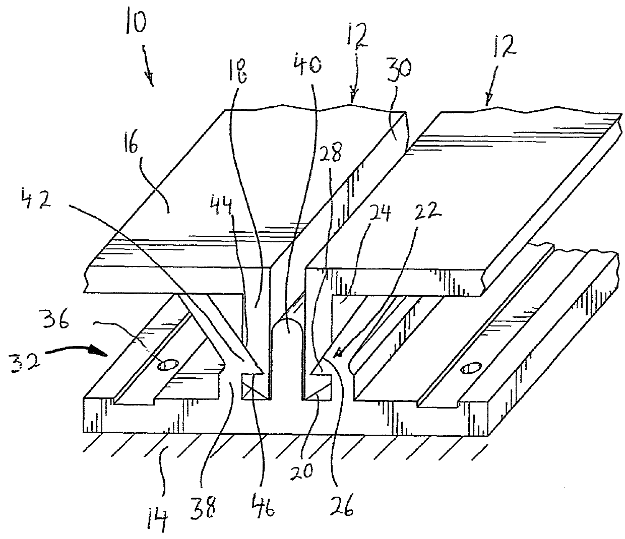
[0057]Referring now to FIGS. 5-7, a system 410 for easily mounting wall panels 12 over an existing wall structure 14 according to the present invention, will now be described. System 410 is similar to system 110 of FIG. 3, although it can be used in an arrangement similar to any of the above described systems 110, 210 and 310, or any other arrangement which is disclosed in U.S. Pat. Nos. 8,833,015, 8,739,483, 8,925,271 and 8,966,849; and pending U.S. patent application Ser. Nos. 14 / 044,606, 14 / 256,384, 14 / 641,097 and 14 / 667,297 to the same inventor herein.

[0058]Specifically, as with system 110, in system 410, each bent end securing wall 438 extending from base section 434 of each main fastening extrusion 432, is mounted to the outside of a respective spacer post wall 440 with a spacing therebetween equal to the thickness of one bent end section 418. There are also barbs 439 on the inner surfaces of spacer post walls 440. However, in system 410, bent end securing walls 438 are rigid,...

second embodiment

[0080]Referring now to FIGS. 17-19, a system 810 for easily mounting wall panels 12 over an existing wall structure 14 according to the present invention, will now be described.

[0081]With system 810, rather than providing a plurality of discrete latch housings, a single elongated latch housing 858 is provided. There are still a plurality of latch bolts 470 therein for insertion in through openings 452 in each bent end section 418 of each wall panel 412. In order to bias latch bolts 470 into the gap between bent end securing wall 438 and spacer post wall 440, a single sinusoidal shaped wave leaf spring 872 is provided between rear surfaces 470a thereof and closed end 862 of latch housing 858, with the peaks 872a on one side in contact with rear surfaces 470a of latch bolts 470, and the peaks 872b on the other side in contact with closed end 862 of latch housing 858, in order to provide a biasing force on latch bolts 470. Of course, a single elongated latch bolt 470 can be provided in...


PUM


Abstract

A system for mounting wall panels to an existing wall structure, includes wall panels, each formed by a main wall panel section and at least two bent end sections; fastening extrusions, each including a base section adapted to be secured to the existing wall structure and a rigid wall extending at an angle therefrom; and a latch arrangement for securing the wall panels to the rigid wall, the latch arrangement including a latch housing, a movable latch member mounted in the latch housing for either engaging within through openings of respective ones of the rigid wall and the bent end sections, or applying a force on each bent end section positioned against a respective rigid wall, and a force application member for moving the movable latch member into a position to cause locking of respective ones of the rigid wall and the bent end sections.

Description

BACKGROUND OF THE INVENTION[0001]The present invention relates generally to a wall system, and more particularly, to a system for easily mounting wall panels over an existing wall structure.[0002]In order to enhance the look of a wall structure, it is known to secure decorative wall panels to the wall structure. However, the securement of wall panels to the wall structure is generally a long and tedious job since it entails using fastening devices such as nails and / or screws to secure the walls panels directly to the wall structure. In addition, the fastening devices are exposed, which can provide an unsightly appearance.[0003]A system that overcomes these problems is disclosed in U.S. Pat. Nos. 8,833,015, 8,739,483, 8,925,271 and 8,966,849; and pending U.S. patent application Ser. Nos. 14 / 044,606, 14 / 256,384, 14 / 641,097 and 14 / 667,297 to the same inventor herein, the entire disclosures of which are incorporated herein by reference. In these patents, each wall panel includes a main ...

Claims


Application Information

Patent Timeline
Patent Type & Authority Patents(United States)
IPC IPC(8): E04B2/00E04F13/072E04F13/08E04F13/24
CPCE04F13/0803E04F13/072E04F13/24E04F13/0812E04F13/0825E04F13/0891E04F13/12
Inventor BILGE, HENRY H.
Owner BILGE HENRY H
Features
  • R&D
  • Intellectual Property
  • Life Sciences
  • Materials
  • Tech Scout
  • Unparalleled Data Quality
  • Higher Quality Content
  • 60% Fewer Hallucinations
Learn More