Scanning camera-based video surveillance system

a video surveillance and camera-based technology, applied in the field of video-based surveillance, can solve the problems of increasing complexity and cost, affecting the efficiency affecting the effectiveness of the individual sensor, so as to achieve the effect of efficient use of the camera and covering large areas

Active Publication Date: 2016-06-07
MOTOROLA SOLUTIONS INC
View PDF27 Cites 9 Cited by
  • Summary
  • Abstract
  • Description
  • Claims
  • Application Information

AI Technical Summary

Benefits of technology

[0005]The present invention is directed to a system and method that solves the problems described above. It harnesses the power of scanning PTZ cameras to cover large areas quickly while still allowing for efficient use of the cameras as surveillance tools.

Problems solved by technology

One common issue facing designers of such security systems is the tradeoff between the number of sensors used and the effectiveness of each individual sensor.
This has the benefit of providing a quick view of the entire area being covered and being inexpensive and easy to manage, but has the drawback of providing poor video resolution and possibly inadequate detail when observing activities in the scene.
On the other extreme, a larger number of narrow-angle cameras can be used to provide greater detail on activities of interest, at the expense of increased complexity and cost.
Furthermore, having a large number of cameras, each with a detailed view of a particular area, makes it difficult for system operators to maintain situational awareness over the entire site.
While these devices can be useful components in a security system, they can also add complexity because they either require human operators for manual control or mindlessly scan back and forth without providing useful information.
This process can be inaccurate and often too slow to catch the target.
If a PTZ camera is given an automated scanning pattern to follow, for example sweeping back and forth along a perimeter fence line, human operators can easily lose interest and miss events that become harder to distinguish from the video's moving background.

Method used


Image

  • Scanning camera-based video surveillance system
  • Scanning camera-based video surveillance system
  • Scanning camera-based video surveillance system

Examples


Embodiment Construction

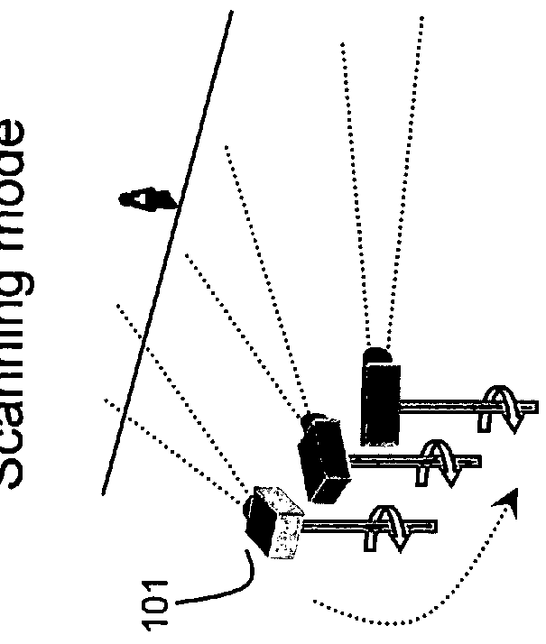
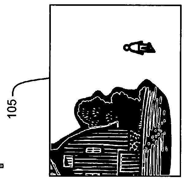
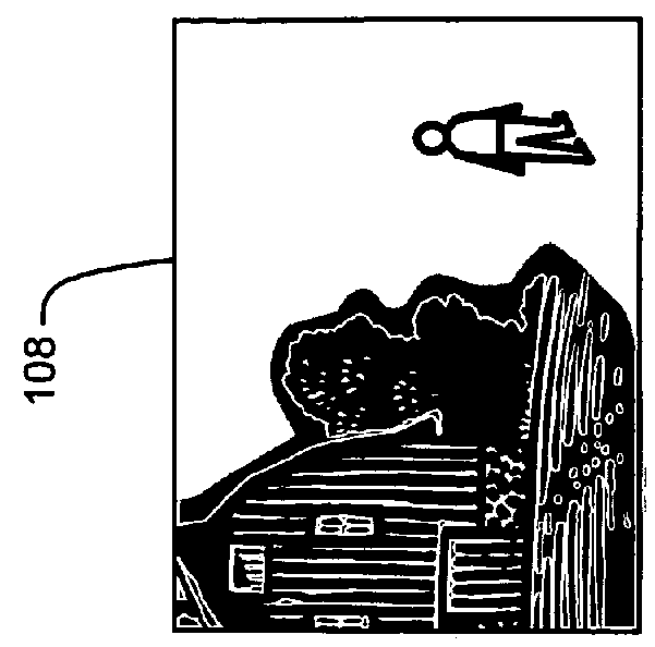
[0036]FIGS. 1A-1C depict a conceptual embodiment of the invention, showing the three different modes in which a single sensing device may operate. While the discussion below considers a single one of the sensing devices shown in FIG. 1A, embodiments of the invention may involve more than one sensing device, as shown, and the discussion is equally applicable to each such sensing device. In scanning mode, pan-tilt-zoom camera 101 follows a predefined scan path to continuously cover a wide area. This scan path may include panning, tilting, and / or zooming. Scanning the camera over a wide area allows for a larger area to be covered than what is visible to the camera when it is stopped at one fixed location. While in scanning mode, moving camera 101 provides frames such as frame 102, showing an example view of the world. Note that the view contains a building and a human target, which appears quite small in the camera's field of view. Once the scanning camera sees a target of interest, wh...


PUM


Abstract

A video surveillance system may include at least one sensing unit capable of being operated in a scanning mode and a video processing unit coupled to the sensing unit, the video processing unit to receive and process image data from the sensing unit and to detect scene events and target activity.

Description

FIELD OF THE INVENTION[0001]The present invention is related to methods and systems for performing video-based surveillance. More specifically, the invention is related to such systems involving sensing devices (e.g., video cameras).BACKGROUND OF THE INVENTION[0002]Many businesses and other facilities, such as banks, stores, airports, etc., make use of security systems. Among such systems are video-based systems, in which a sensing device, like a video camera, obtains and records images within its sensory field. For example, a video camera will provide a video record of whatever is within the field-of-view of its lens. Such video images may be monitored by a human operator and / or reviewed later by a human operator. Recent progress has allowed such video images to be monitored also by an automated system, improving detection rates and saving human labor.[0003]One common issue facing designers of such security systems is the tradeoff between the number of sensors used and the effectiv...

Claims


Application Information

Patent Timeline
Patent Type & Authority Patents(United States)
IPC IPC(8): H04N7/18G08B13/196G06K9/00
CPCH04N7/181G08B13/1968G08B13/19608G08B13/19613G08B13/19641G08B13/19656G08B13/19682G08B13/19689G06K9/00771G06V20/52H04N23/69G08B13/1963
Inventor CHOSAK, ANDREW J.BREWER, PAUL C.EGNAL, GEOFFREYGUPTA, HIMAANSHUHAERING, NIELSLIPTON, ALAN J.YU, LI
Owner MOTOROLA SOLUTIONS INC
Why Eureka
Try Eureka