Conveying system having a detection area

a detection area and conveying system technology, applied in the field of conveying systems, can solve the problems of slow system, erroneous elevator call or other service request registration, unreliable system based on bio-identification, etc., and achieve the effect of facilitating and speeding up the arrival of passengers, avoiding erroneous or accidental call registration, and easy integration into connection

Active Publication Date: 2016-06-14
KONE CORP
View PDF25 Cites 20 Cited by
  • Summary
  • Abstract
  • Description
  • Claims
  • Application Information

AI Technical Summary

Benefits of technology

[0015]In one embodiment of the invention the user interface of a transport device is configured dynamically on the basis of determined service profiles. As a result of the embodiment, travel can be facilitated e.g. by personalizing user interfaces for specific passengers. Also access control can be improved by taking into account in the user interfaces the access rights of one or more passengers.
[0019]With the solution according to the invention numerous advantages are achieved compared to prior-art solutions. The solution according to the invention is simple and easy to integrate into connection with a conveying system. Identifiers are read only when a passenger is in a detection area, in which case identification is accurate and registration of erroneous or accidental calls is avoided. The solution according to the invention is also user-friendly because the identifier does not need to be taken out for giving a service request, but instead the passenger can keep his / her identifier e.g. in his / her pocket when moving around in the building. The user interfaces and the transport services of the conveying system can also be personalized to specific passengers, which facilitates and speeds up the arrival of a passenger at his / her destination. With the solution according to the invention access control can be improved because the transfer of passengers from one location to another can be monitored better than before and e.g. “tail-gating” can be detected, in which tail-gating a passenger follows a second passenger to a location to which the second passenger has an access right but the follower does not.

Problems solved by technology

A number of drawbacks are, however, connected to the prior-art solutions described above.
Systems based on bio-identifiers are often unreliable and slow systems for use in elevator systems and other such conveying systems.
A so-called crosstalk problem, on the other hand, wherein an identifier in the possession of a passenger is simultaneously detected by two or more reader devices e.g. disposed on different floors, is connected to remotely-read identifiers.
This easily leads to the registration of erroneous elevator calls or of other service requests.
To minimize the crosstalk problem, reader devices must be located in a building with particular care and accuracy, which of course raises costs.
Remotely-read identifiers can also produce useless elevator calls when a passenger arriving in an elevator lobby does not want to use the elevators but instead calls into an elevator lobby for some other reason.
The use of identifiers to be read from close range, on the other hand, requires that the passenger takes out the identifier in his / her possession and takes it “manually” to the reader device, which is impractical and slows down travel.

Method used


Image

  • Conveying system having a detection area
  • Conveying system having a detection area
  • Conveying system having a detection area

Examples


Embodiment Construction

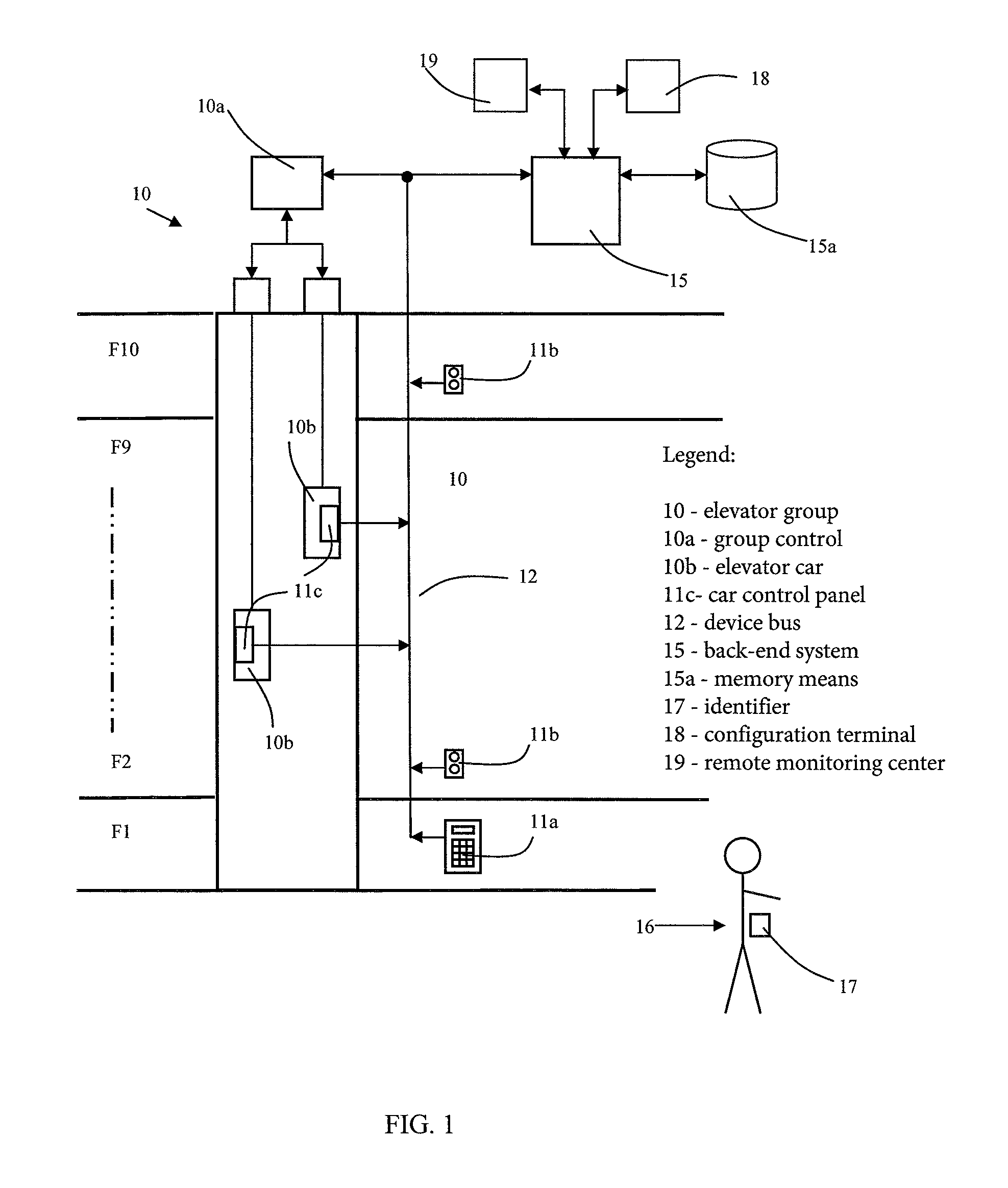
[0023]FIG. 1 presents one conveying system according to the invention, wherein an elevator group 10 serves the floors F1-F10 of a building. The elevator group comprises two elevators, up / down call pushbuttons 11b on the floors F2-F10 for calling an elevator car 10b to a call floor, a destination call panel 11a for giving destination calls in the entrance lobby floor F1, and car command panels 11c for giving car commands in the elevator cars 10b. The call panels 11 (11a-11d) that function as the user interfaces of an elevator group are connected to a device bus 12, via which the back-end system 15, the group control 10a of the elevator group and the call panels 11 can transmit data to each other. The device bus 12 can be any data transfer bus whatsoever suited to the purpose, e.g. a wireless local area network. The group control 10a and the back-end system 15 form the control system of the conveying system.

[0024]The back-end system 15 comprises a processor unit, application software ...


PUM


Abstract

A conveying system and a method for registering service requests in a conveying system, including at least one transport device, is provided. A detection area bounded on a floor surface is in connection with the transport device, in which detection area the identification data contained in the personal identifiers of passengers is read. The service profiles of passengers who have arrived in the detection area and / or who have left the detection area are determined on the basis of the identification data, and a service request according to the service profiles is registered for transporting and / or admitting passengers in the detection area to the location indicated by the service request.

Description

CROSS REFERENCE TO RELATED APPLICATIONS[0001]This application is a Bypass Continuation of PCT International Application No. PCT / FI2011 / 051151 filed on Dec. 23, 2011, which claims priority under 35 U.S.C §119(a) to Patent Application No. 20106386 filed in Finland on Dec. 30, 2010, all of which are hereby expressly incorporated by reference into the present application.FIELD OF THE INVENTION[0002]The invention relates to conveying systems. More particularly the invention relates to the registration of service requests in elevator systems and other such conveying systems by means of a personal identifier.BACKGROUND OF THE INVENTION[0003]With regard to elevator systems, call-giving solutions are known in which a passenger gives calls to the elevators of an elevator system by means of a personal identifier, e.g. by means of an RFID identifier (Radio Frequency Identifier). For reading the data contained in an identifier, the elevator system must be provided with reader devices, into the d...

Claims


Application Information

Patent Timeline
Patent Type & Authority Patents(United States)
IPC IPC(8): B66B1/20B66B1/34B66B1/46
CPCB66B1/3461B66B1/468B66B2201/4653
Inventor SALMIKUUKKA, JUKKANEVALAINEN, MIRVA
Owner KONE CORP
Why Eureka
Try Eureka