Optical pumping magnetometer
a magnetometer and optical technology, applied in the field of magnetometers, can solve the problems of inability to efficiently excite the alkali metal gas in the glass cell, easy polarization of optical paths, uneven temperature of optical fibers, etc., and achieve the effect of preventing collapse of polarization or fluctuation and stable operation of optical paths
- Summary
- Abstract
- Description
- Claims
- Application Information
AI Technical Summary
Benefits of technology
Problems solved by technology
Method used
Image
Examples
first embodiment
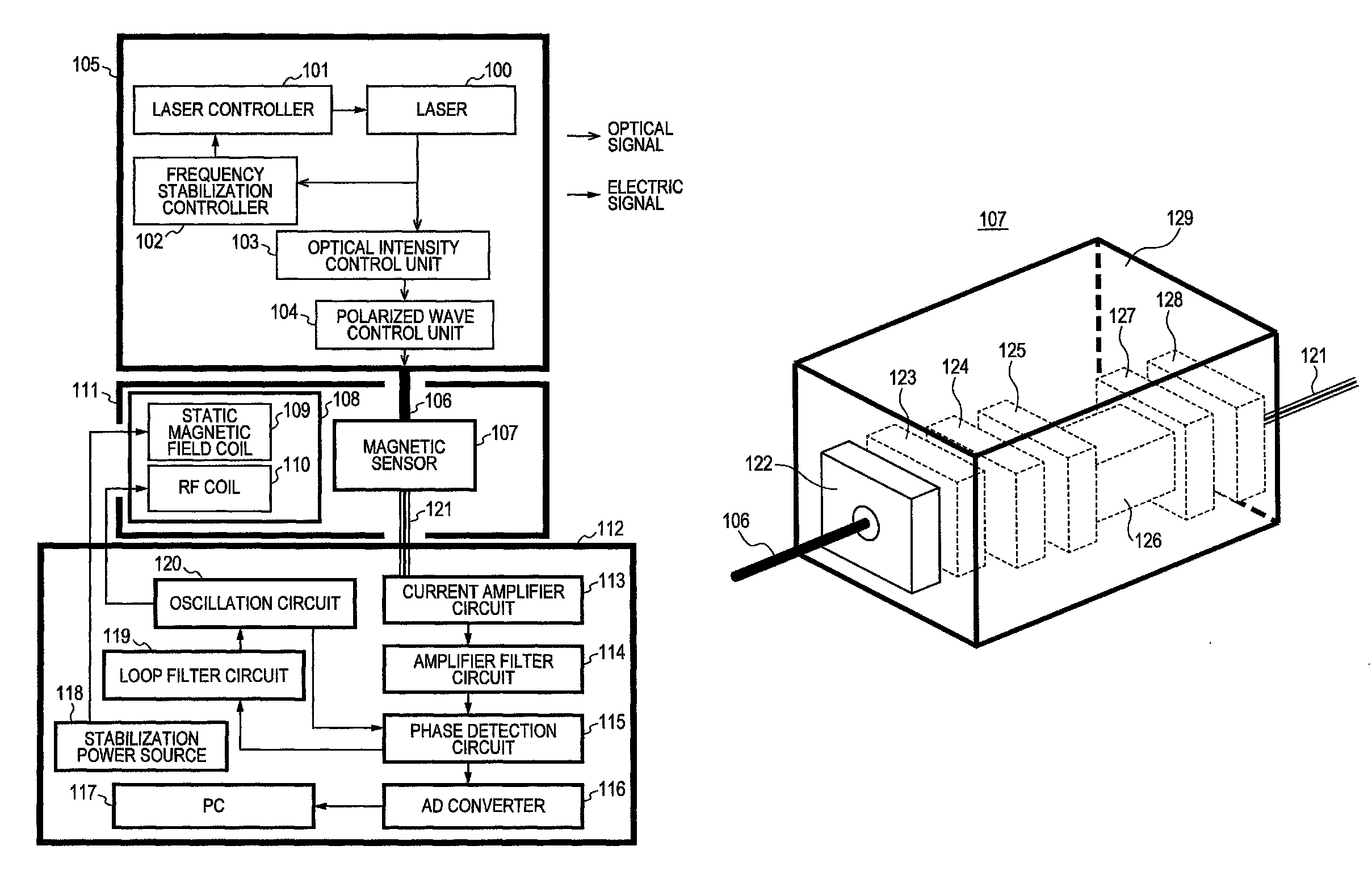
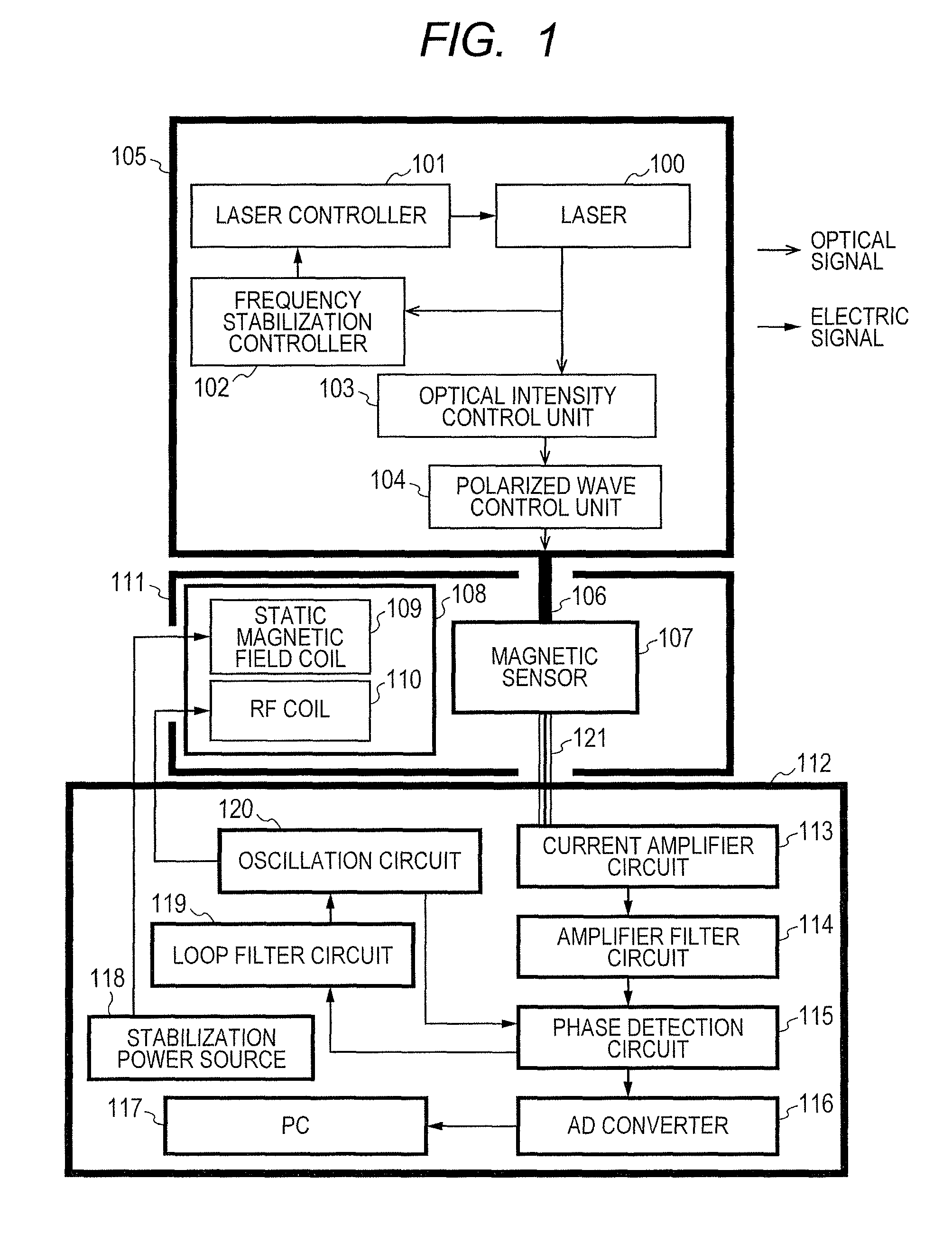
[0027]FIG. 1 schematically shows the configuration of a magnetometer according to a first embodiment of the present invention. The magnetometer has a light source 105, a coil 108, a magnetic sensor 107, and a signal control processor 112.
[0028]As the light source, a lamp may be used, however, it is preferable to use a stable and high-performance laser. Accordingly, a laser 100 is used in the light source 105 according to the present embodiment.
[0029]It is necessary for the laser to operate the optical pumping magnetic sensor to satisfy the following conditions. It is necessary to perform oscillation around a frequency of excitation transition (line D1 and line D2) of alkali metal entered the glass cell in the magnetic sensor. It is necessary to perform single mode laser oscillation at a stable oscillation frequency. The laser beam width must be equal to or less than a natural width of alkali metal atoms. It is necessary to output a laser beam to sufficiently excite the alkali metal ...
second embodiment
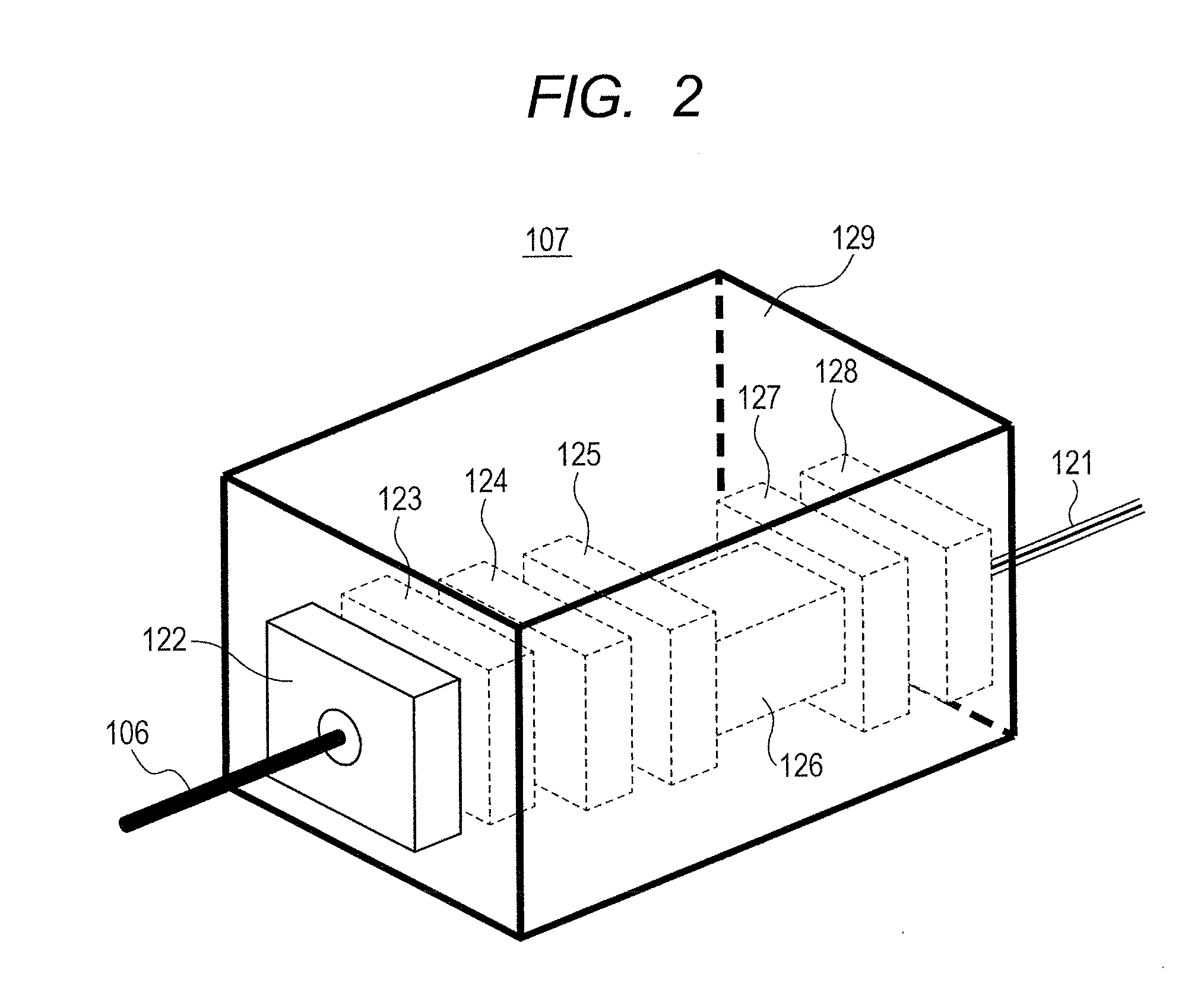
[0040]In a second embodiment of the present invention, the configuration of the magnetic sensor is different from that in the above-described first embodiment. FIG. 3 shows the structure of the magnetic sensor 131 according to the second embodiment. In comparison with the magnetic sensor 107 according to the first embodiment as shown in FIG. 2, the difference is that the photodetector 128 is omitted, and the laser beam passed through the magnetic-sensor glass cell 126 is collected with the light collecting lens 127 at an end surface of the multi-mode optical fiber 130 and outputted with the multi-mode optical fiber 130 to the outside the magnetic sensor 131. The multi-mode optical fiber 130 is attached to the non-magnetic case 129 with a non-magnetic fiber connector 152. The structure from the polarized wave holding optical fiber 106 to introduce the excitation light to the glass cell 126 is the same as that of the magnetic sensor 107 according to the first embodiment in FIG. 2.
[004...
third embodiment
[0044]In a third embodiment of the present invention, the magnetic sensor 107 according to the first embodiment has a heat preserving mechanism heat preserving mechanism. FIG. 5 shows the structure of a magnetic sensor 134 in the magnetometer according to the third embodiment. In comparison with the magnetic sensor 107 according to the first embodiment shown in FIG. 2, the difference is that chambers 138 and 139 which warm water flows in are provided in an outer surface of a glass wall of the magnetic-sensor glass cell 126. The magnetic-sensor non-magnetic case 129 is provided with a warm water inflow port 135 connected to the chamber 138. The chamber 138 is connected to the chamber 139 via a connection unit 137, and further, the chamber 139 is connected to a warm water outflow port 136 so as to pass warm water through. The structure from the polarized wave holding optical fiber 106 to introduce the excitation light to the magnetic-sensor photodetector 128 to detect the laser beam p...
PUM
 Abstract
Description
Claims
Application Information
 - R&D
- Intellectual Property
- Life Sciences
- Materials
- Tech Scout
- Unparalleled Data Quality
- Higher Quality Content
- 60% Fewer Hallucinations
Browse by: Latest US Patents, China's latest patents, Technical Efficacy Thesaurus, Application Domain, Technology Topic, Popular Technical Reports.
© 2025 PatSnap. All rights reserved.Legal|Privacy policy|Modern Slavery Act Transparency Statement|Sitemap|About US| Contact US: help@patsnap.com


