Heat treating apparatus for powder particles and method of producing toner

a technology of heat treatment apparatus and powder particles, which is applied in the direction of lighting and heating apparatus, instruments, developers, etc., can solve the problems of inability to produce stable, coarse particles, and apparatus is not preferable for toner production, so as to improve the space efficiency of the unit layout, reduce the number of supplying units, and reduce the effect of consuming energy

Active Publication Date: 2016-06-21
CANON KK
View PDF31 Cites 38 Cited by
  • Summary
  • Abstract
  • Description
  • Claims
  • Application Information

AI Technical Summary

Benefits of technology

[0018]According to the present invention, powder particles can be heat-treated in a nearly uniform state, and coalesced particles and particles having an extremely high circularity can be prevented from being generated, even if a throughput or an amount to be treated is increased.
[0019]Further, according to the present invention, the number of supplying units can be minimized and in particular space efficiency on an unit layout can be enhanced.
[0020]Further features of the present invention will become apparent from the following description of exemplary embodiments with reference to the attached drawings.

Problems solved by technology

However, if excessive heat is applied to a toner in a method of utilizing heat, toner particles coalesce to each other to cause coarse particles.
However, if members in the apparatus receive heat to accumulate heat, a toner is fused to the members which accumulate heat, thereby not enabling stable production.
Thus, the apparatus is not preferable in production of a toner.
However, since such a configuration requires providing a plurality of raw material jet nozzles, grows in size in terms of an apparatus configuration and requires compressed gas for supplying a raw material in a more amount, the configuration is not preferable in terms of production energy.
In addition, since raw materials are linearly jetted to annular hot air to thereby generate a loss in a treating portion, the configuration is not efficient in increasing an amount to be treated.
However, since the plurality of supplying parts to be usually considered (see, FIG. 9) cause an increase in number of supplying apparatuses by the number of the supplying parts, problems are an increase in space efficiency (occupied area by an apparatus for ensuring a desired amount of production) as well as a decrease in energy efficiency and maintenance load.
Further, in the case where variation in amounts to be supplied from the plurality of supplying parts is generated, there is a problem such as an increase in coalesced particles in treating.
In addition, a branching method described in Patent Literature 5 causes a difference in flow speed in a pipe in the case of having no choice but to bend the pipe from the restrictions of layout, and the method has difficulty in uniformity of distribution.

Method used


Image

  • Heat treating apparatus for powder particles and method of producing toner
  • Heat treating apparatus for powder particles and method of producing toner
  • Heat treating apparatus for powder particles and method of producing toner

Examples


example 1

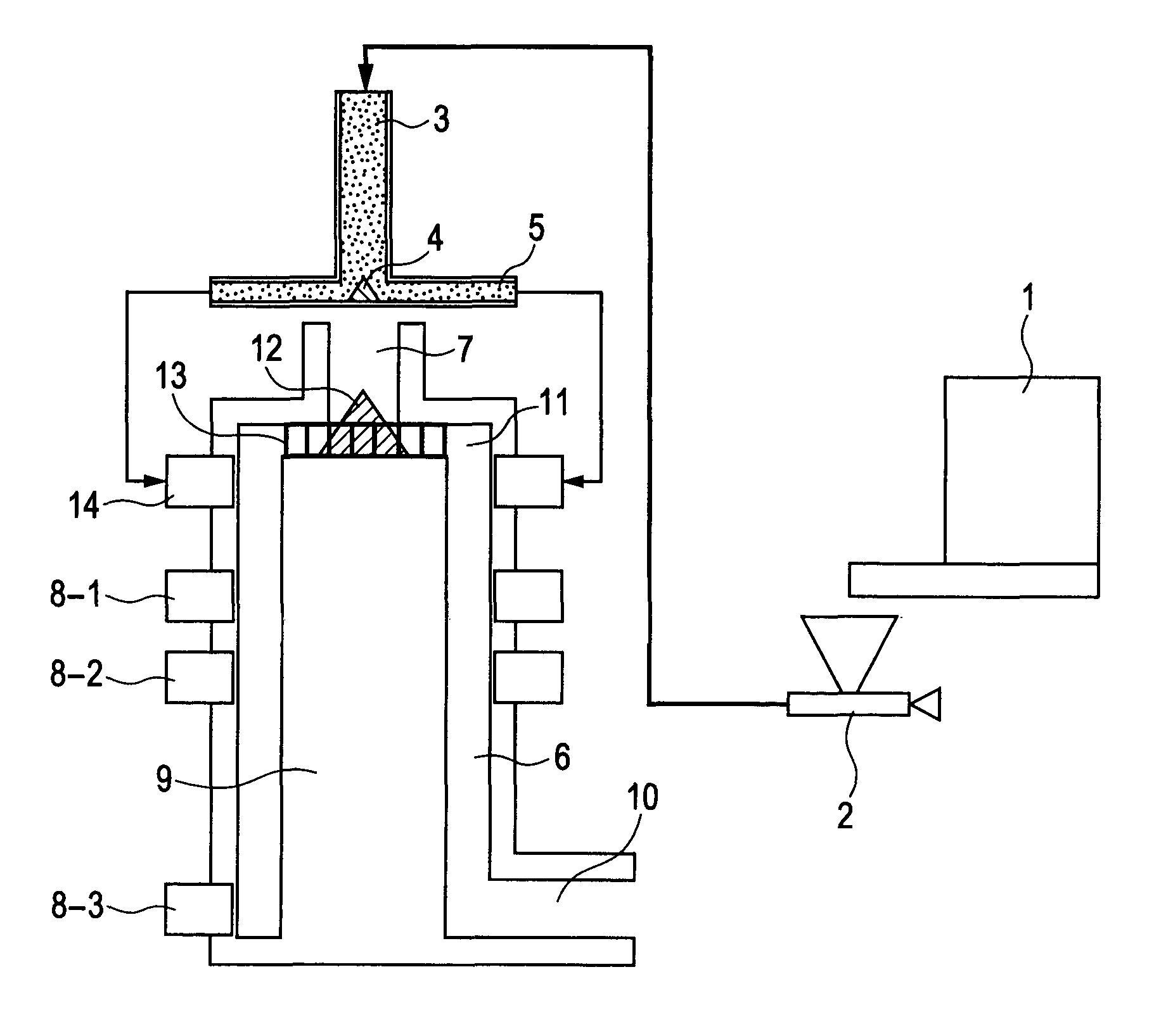
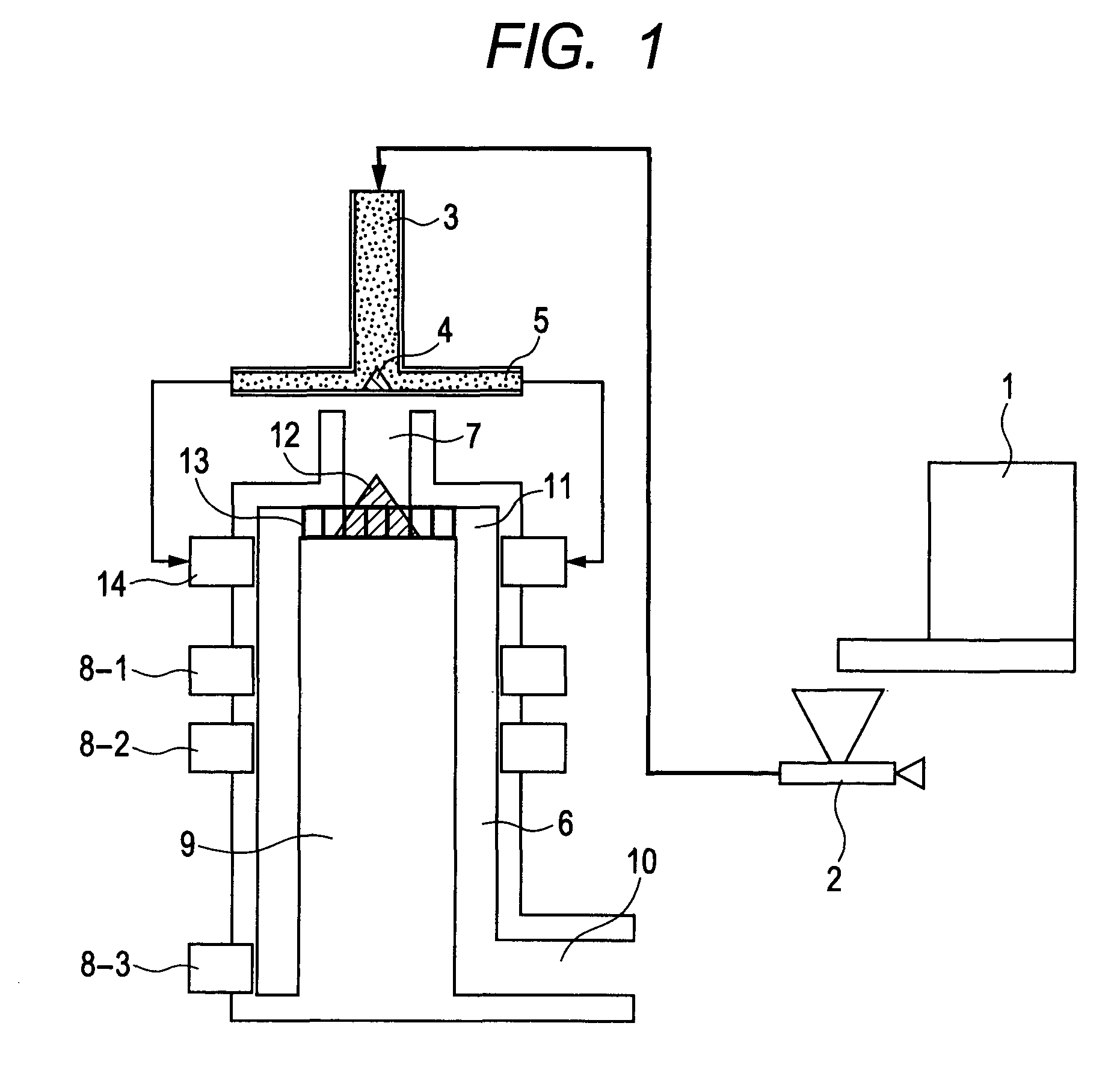
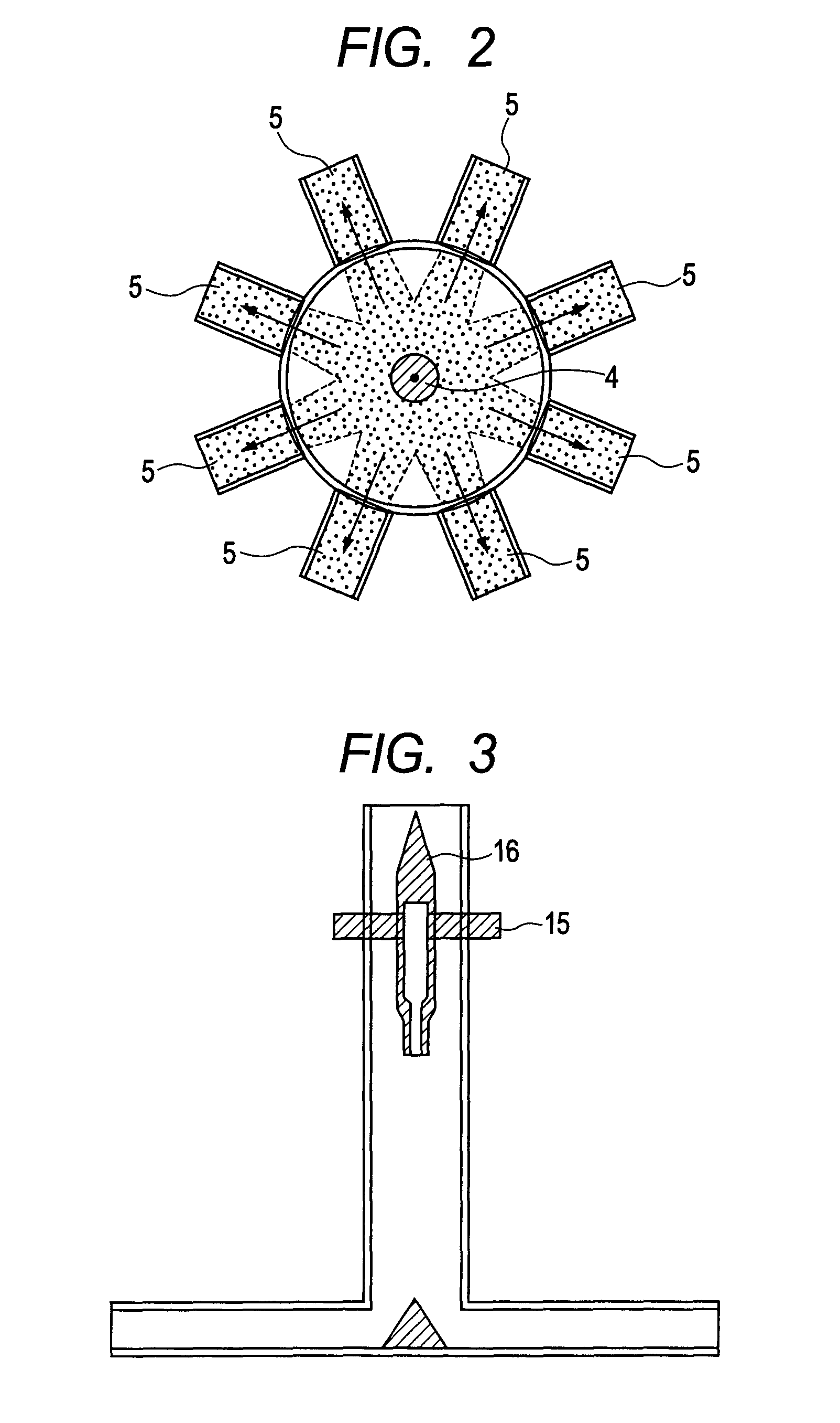
[0129]The heat treating apparatus illustrated in FIG. 1 was used to perform a heat treatment. As the raw material-supplying unit, a unit in which a branching flow path for supplying raw materials was branched in 8 directions, as illustrated in FIG. 2, was used. An internal structure of the raw material-supplying unit having eight flow paths in FIG. 2 will now be described. An internal diameter of the supplying tube 5 is 50 mm in diameter, and the tube 5 is connected to the supplying port 14 (diameter 50 mm) of the heat treating apparatus through a pipe. The raw material-supplying unit in FIG. 2 has eight triangular edges arranged thereon in order to introduce powder particles to the supplying tube 5 in multiple ways. The distributing member 4 used had a conic shape, a height of 40 mm, and a diameter of 40 mm. The dispersion air-supplying member illustrated in FIG. 3 was used in the inside of the introducing tube of the raw material-supplying unit. Air was introduced from the dispers...

example 2

[0151]A heat treatment of toner particles A was performed by using the heat treating apparatus illustrated in FIG. 1 in the same manner as in Example 1 except that a flow speed of each supplying port was adjusted within 10.0±0.3 m / s by the flow rate adjustment mechanism. A configuration of the raw material-supplying unit was summarized in Table 1, flow speeds of flow paths A to H of the supplying tube of the raw material-supplying unit were summarized in Table 2, and a particle diameter and evaluation of the heat-treated particles obtained were summarized in Table 3.

example 3

[0152]A heat treatment of toner particles A was performed by using the heat treating apparatus illustrated in FIG. 1 in the same manner as in Example 1 except that a flow speed of each supplying port was adjusted within 10.0±0.5 m / s by the flow rate adjustment mechanism. A configuration of the raw material-supplying unit was summarized in Table 1, flow speeds of flow paths A to H of the supplying tube of the raw material-supplying unit were summarized in Table 2, and a particle diameter and evaluation of the heat-treated particles obtained were summarized in Table 3.


PUM

PropertyMeasurementUnit
flow rateaaaaaaaaaa
flow speedaaaaaaaaaa
diameteraaaaaaaaaa

Abstract

A heat treating apparatus for powder particles containing a binder resin and a colorant, the heat treating apparatus including: a treating chamber in which a heat treatment of the powder particles is performed; a raw material-supplying unit for supplying the powder particles to the treating chamber; a hot air-supplying unit that supplies hot air to the treating chamber; a cold air-supplying unit that supplies cold air for cooling the heat-treated powder particles; and a recovering unit that recovers the heat-treated powder particles. The raw material-supplying unit includes an introducing tube and a distributing member, and the distributing member is provided with a protruding member on a portion opposite to an outlet portion of the introducing tube, and the distributing member includes a supplying tube including two or more flow paths that extend radially outwardly from the protruding member to a wall surface of the treating chamber.

Description

TECHNICAL FIELD[0001]The present invention relates to a heat treating apparatus for powder particles for obtaining a toner for use in an image forming method such as an electrophotographic method, an electrostatic recording method, an electrostatic printing method, or a toner jet recording method; and a method of producing a toner by using the heat treating apparatus.BACKGROUND ART[0002]In recent years, as image quality and precision in copiers and printers have been higher, requirements for the performance of a toner as a developer have been also even severer, and thus a toner having a smaller particle diameter and a sharper particle size distribution with containing no coarse particles and with few fine particles has been being demanded.[0003]Further, as a transferring material for copiers and printers, there has been a need for responding to a variety of materials other than common paper, and the toner has been required to exhibit improved transferring properties. Thus, there hav...

Claims


Application Information

Patent Timeline
Patent Type & Authority Patents(United States)
IPC IPC(8): G03G9/08F26B17/10
CPCG03G9/0804G03G9/0806G03G9/0808G03G9/0815F26B17/103G03G9/0802G03G9/081
Inventor MIZO, YUICHIMINAGAWA, HIRONORIKOBORI, TAKAKUNITAKENAKA, KOHJIOHTSU, TAKESHIHAGIWARA, JUNICHIITO, DAISUKEKAWAKITA, KUNIHIKO
Owner CANON KK
Why Eureka
Try Eureka