
Method and apparatus for diagnosing fault within fuel cell stack

a fuel cell and stack fault technology, applied in resistance/reactance/impedence, electrochemical generators, instruments, etc., can solve the problems of affecting the entire performanceaffecting the accuracy of diagnosis, and it is substantially difficult to quantitatively measure the cause of the drop in cell voltage. , to achieve the effect of accurately diagnosing the fault of the fuel cell stack, reducing the size of the apparatus, and reducing the cost of apparatus production

Active Publication Date: 2016-06-21
KANGNAM UNIV IND ACAD COOPERATION FOUND +1
View PDF9 Cites 3 Cited by
  • Summary
  • Abstract
  • Description
  • Claims
  • Application Information

AI Technical Summary

Benefits of technology

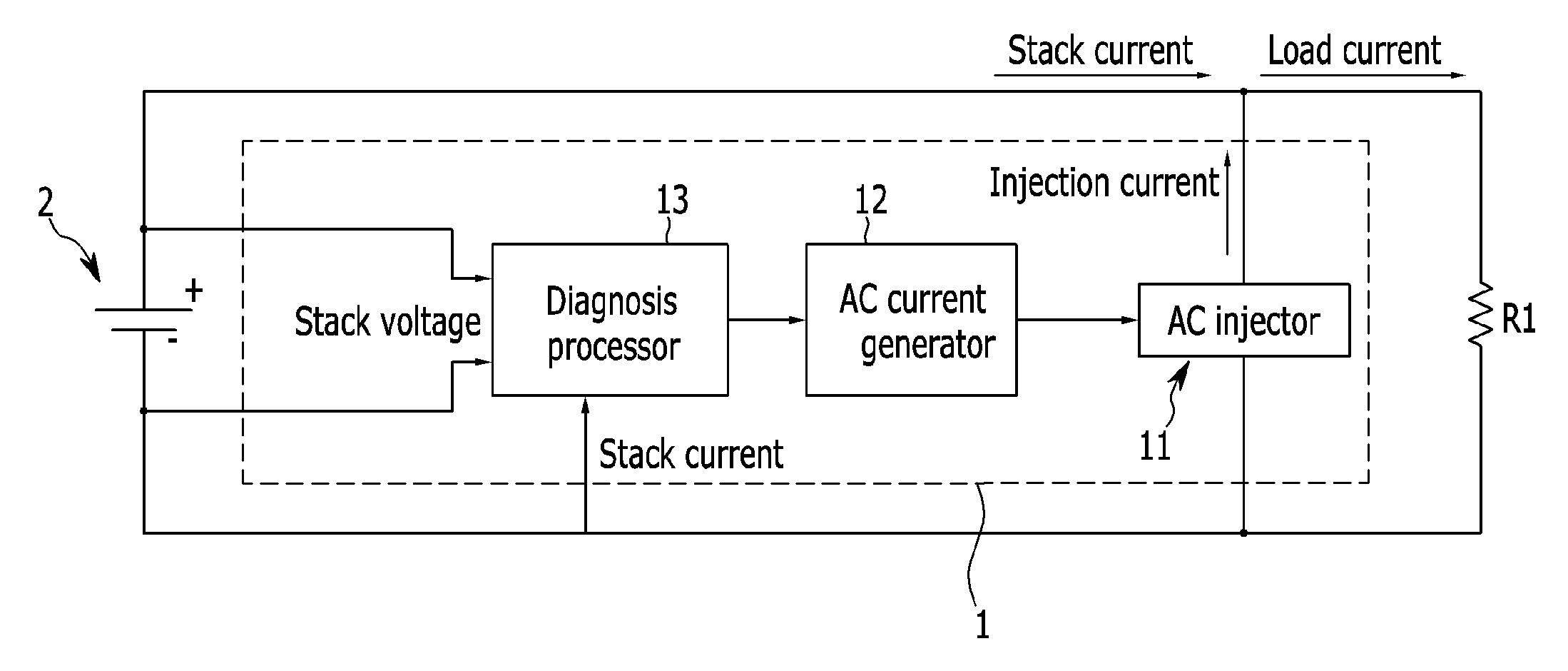
The present invention is about a method and device for diagnosing the cause of a drop in voltage in a fuel cell stack. This invention can measure the drop in voltage and determine the cause simultaneously using a single device, reducing the size and cost of the diagnostic apparatus and improving accuracy. This also means that the optimum frequency for diagnosing both the drop in voltage and the cause can be determined at the same time.

Problems solved by technology

However, when performance deterioration or a failure occurs in any one cell among the unit cells that make up the fuel cell stack, the entire performance of the fuel cell stack is deteriorated and thus, a stable operation is not provided.
Even though the THDA method may easily detect a drop in cell voltage, it is substantially difficult to quantitatively measure what has caused the drop in cell voltage.
However, this method diagnoses the humidification state by measuring the load on a stack, but does not diagnose the drop in cell voltage.

Method used


Image

  • Method and apparatus for diagnosing fault within fuel cell stack
  • Method and apparatus for diagnosing fault within fuel cell stack
  • Method and apparatus for diagnosing fault within fuel cell stack

Examples


Embodiment Construction

[0027]In the following detailed description, only certain exemplary embodiments of the present invention have been shown and described, simply by way of illustration. As those skilled in the art would realize, the described embodiments may be modified in various different ways, all without departing from the spirit or scope of the present invention. Accordingly, the drawings and description are to be regarded as illustrative in nature and not restrictive. Like reference numerals designate like elements throughout the specification.

[0028]In the specification, unless explicitly described to the contrary, the word “comprise / include” and variations such as “comprises / includes” or “comprising / including”, will be understood to imply the inclusion of stated elements but not the exclusion of any other elements.

[0029]It is understood that the term “vehicle” or “vehicular” or other similar term as used herein is inclusive of motor vehicles in general such as passenger automobiles including sp...


PUM

PropertyMeasurementUnit
frequencyaaaaaaaaaa
frequencyaaaaaaaaaa
frequencyaaaaaaaaaa

Abstract

To diagnose a fault of a fuel cell stack, an alternating current having a first optimal frequency of a first frequency domain to diagnose a drop in cell voltage and an alternating current having a second optimal frequency of a second frequency domain to diagnose a cause of the drop in cell voltage are supplied to the fuel cell stack are provided. A distortion rate is then calculated based on voltage of the fuel cell stack according to the alternating current of the first optimal frequency, and the drop in cell voltage is diagnosed based on the calculated distortion rate. Also, impedance is calculated based on voltage and a current of the fuel cell stack according to the alternating current of the second optimal frequency and amount of water is calculated based on the calculated in the fuel cell stack, and the cause of the drop in cell voltage is diagnosed based on the calculated impedance and amount of water.

Description

CROSS-REFERENCE TO RELATED APPLICATION[0001]This application claims priority to and the benefit of Korean Patent Application No. 10-2012-0143883 filed in the Korean Intellectual Property Office on Dec. 11, 2012, the entire contents of which are incorporated herein by reference.BACKGROUND[0002](a) Field of the Invention[0003]The present invention relates to a method and an apparatus to diagnose a fault of a fuel cell stack.[0004](b) Description of the Related Art[0005]A fuel cell is a type of battery that directly converts chemical energy generated by oxidation of fuel to electrical energy which can be utilized by any number of devices. For the most part, a fuel cell is identical to a chemical cell in that it uses an oxidation and reduction reaction to produce energy. However, in a fuel cell, reactants are intermittently supplied from an outside source and thus, reaction products are consecutively removed from a fuel cell system. In a chemical cell, however, the battery reaction is p...

Claims


Application Information

Patent Timeline
Patent Type & Authority Patents(United States)
IPC IPC(8): G01N27/416H01M8/04
CPCH01M8/04679H01M8/04492H01M8/04649Y02E60/50G01R27/00G01R31/36H01M8/04
Inventor JEONG, KWI SEONGKIM, SAE HOONKIM, UCK SOOPARK, HYUN-SEOKLEE, YOUNG-HYUN
Owner KANGNAM UNIV IND ACAD COOPERATION FOUND
Learn More