Spring clip for shielding of electrical connectors

a shielding and connector technology, applied in the direction of coupling contact members, coupling device connections, electrical apparatus, etc., can solve the problems of undesired interference signals, adverse effects on shielding effectiveness, and insufficient contact, so as to avoid damage or deformation, the stability and strength of the grounding finger is not adversely affected, and the effect of sufficient robustness

Active Publication Date: 2016-06-21
ITT MFG ENTERPRISES LLC
View PDF25 Cites 7 Cited by
  • Summary
  • Abstract
  • Description
  • Claims
  • Application Information

AI Technical Summary

Benefits of technology

[0005]Against this background, described herein is a grounding finger for highly efficient shielding of plug connections of this kind, with which grounding finger the mutual contact between the grounding finger and the elements of the plug connection is further improved and transfer resistances which are as low as possible are produced in every situation.
[0006]According to the present invention, a grounding finger for shielding at an electrical connection between a plug connector and a mating plug connector of an electrical line, having a sleeve-like support element is provided, which grounding finger has a first outer edge and a second outer edge, axial connecting webs in relation to the longitudinal axis of the plug connection being provided between said outer edges, and also has a plurality of spring limbs or spring elements which act radially outward and, at least at one end, are connected to one of the edges in order to generate a spring-loaded contact force to the outer element of the plug connection. The grounding finger according to aspects of the invention is distinguished in that some of the connecting webs are interrupted and are formed in each case with at least one contact lug which faces radially inward. The connecting webs, which are provided, for example, in each case alternately with the spring limbs over the circumference of the grounding finger, establish a connection between the first and second outer edges, so that the grounding finger has a rectangular shape which is substantially closed to the outside. According to aspects of the invention, at least some of the connecting webs are interrupted and are formed in each case with at least one additional contact lug, which extends radially inward from the grounding finger in the direction of the inner plug connector element, at the point of the interruption. While the spring limbs provide an outwardly acting contact force on the corresponding element of the plug connection, increased contact forces are also generated on the inside against the inner element of the plug connection by the additional contact lugs according to aspects of the invention which are directed inward from the plug connection. The inwardly directed contact lugs specifically increase the pressure against the inner element of the plug connection, so that production of transfer resistances is largely avoided at this point too. The grounding finger, which is usually inserted into an accommodation groove, therefore bears securely against the two elements of the plug connection with a kind of pretensioning force. There are therefore considerably lower transfer resistances in the shielding at the interface between the plug connector and the mating plug connector in comparison to conventional grounding fingers of this kind for electrical plug connections. Nevertheless, the grounding finger according to aspects of the invention is considered to be comparatively simple in terms of its structural configuration and can be easily produced with a correspondingly reduced level of expenditure. Furthermore, no additional elements or components are required in order to realize a secure contact transition at the shielding of the plug connection.
[0007]According to an advantageous refinement of the invention, the interrupted connecting webs of the grounding finger are separated approximately in the center, and in each case two axially opposite contact lugs are provided in an approximately central region of the support element, in each case in a symmetrical manner. That is to say, the non-continuous connecting webs, which are provided with an aperture in their central section by means of punching for example, are formed with in each case two opposite contact lugs which protrude radially inward and which, in the fitted state, bear and are pressed firmly against the inner element of the plug connection. In this way, the contact-connection of the shielding is further optimized since in each case two contact lugs are provided at the respective points of the interrupted connecting webs. Contact of the grounding finger between the two elements of the plug connection, specifically the plug connector and a mating plug connector, is also improved as a result since unintentional or undesired inclined installation and a change in position are reliably avoided as a result.

Problems solved by technology

However, it has been found in some applications that a grounding finger of this kind or a shielding contact spring of this kind does not ensure sufficient contact with the two elements of the plug connection, the inner plug connector and the outer mating plug connector.
This has an adverse effect on the effectiveness of the shielding and leads to undesired interference signals.

Method used


Image

  • Spring clip for shielding of electrical connectors
  • Spring clip for shielding of electrical connectors
  • Spring clip for shielding of electrical connectors

Examples


Embodiment Construction

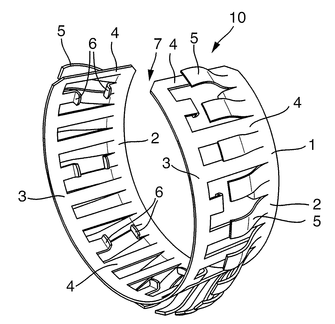
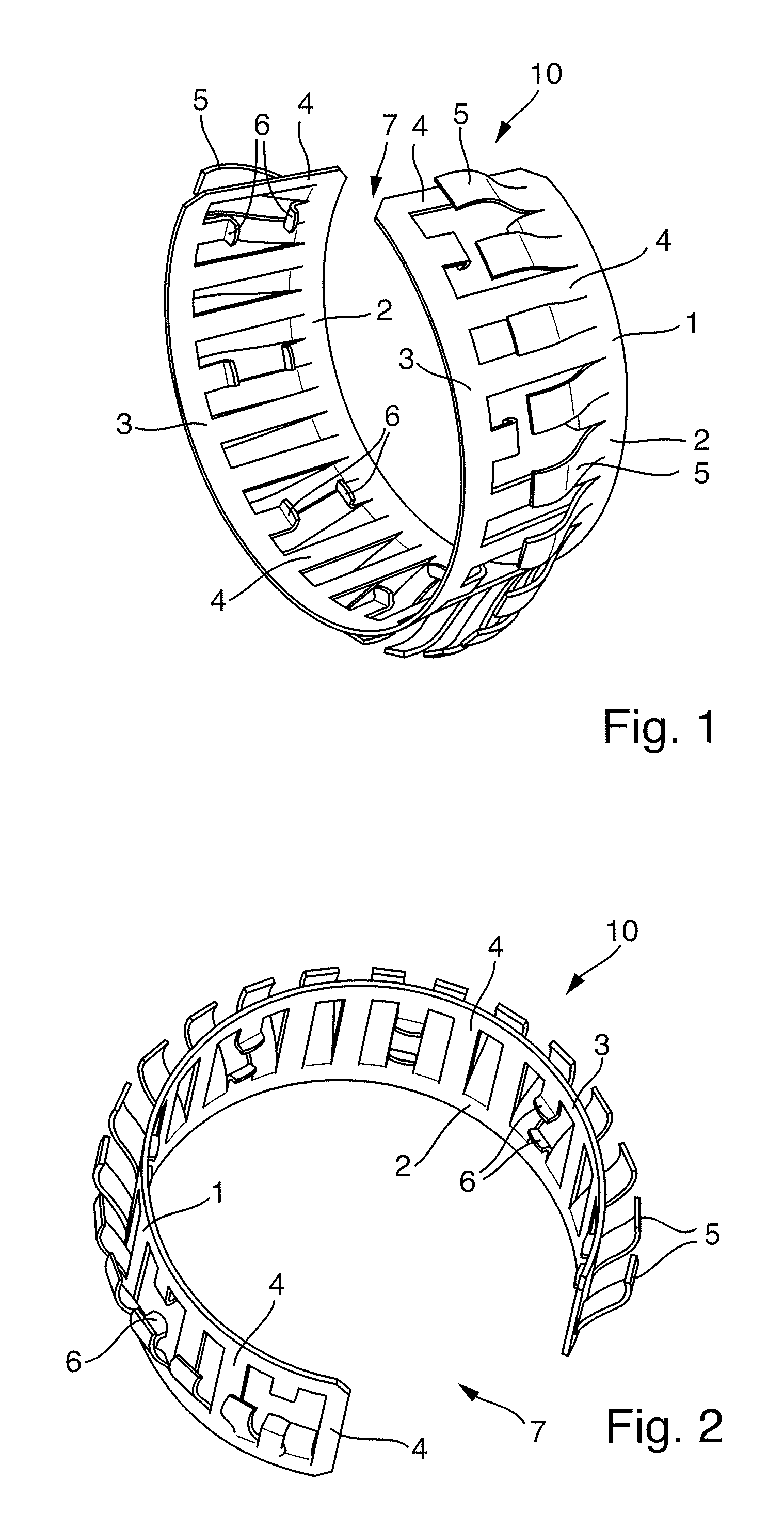
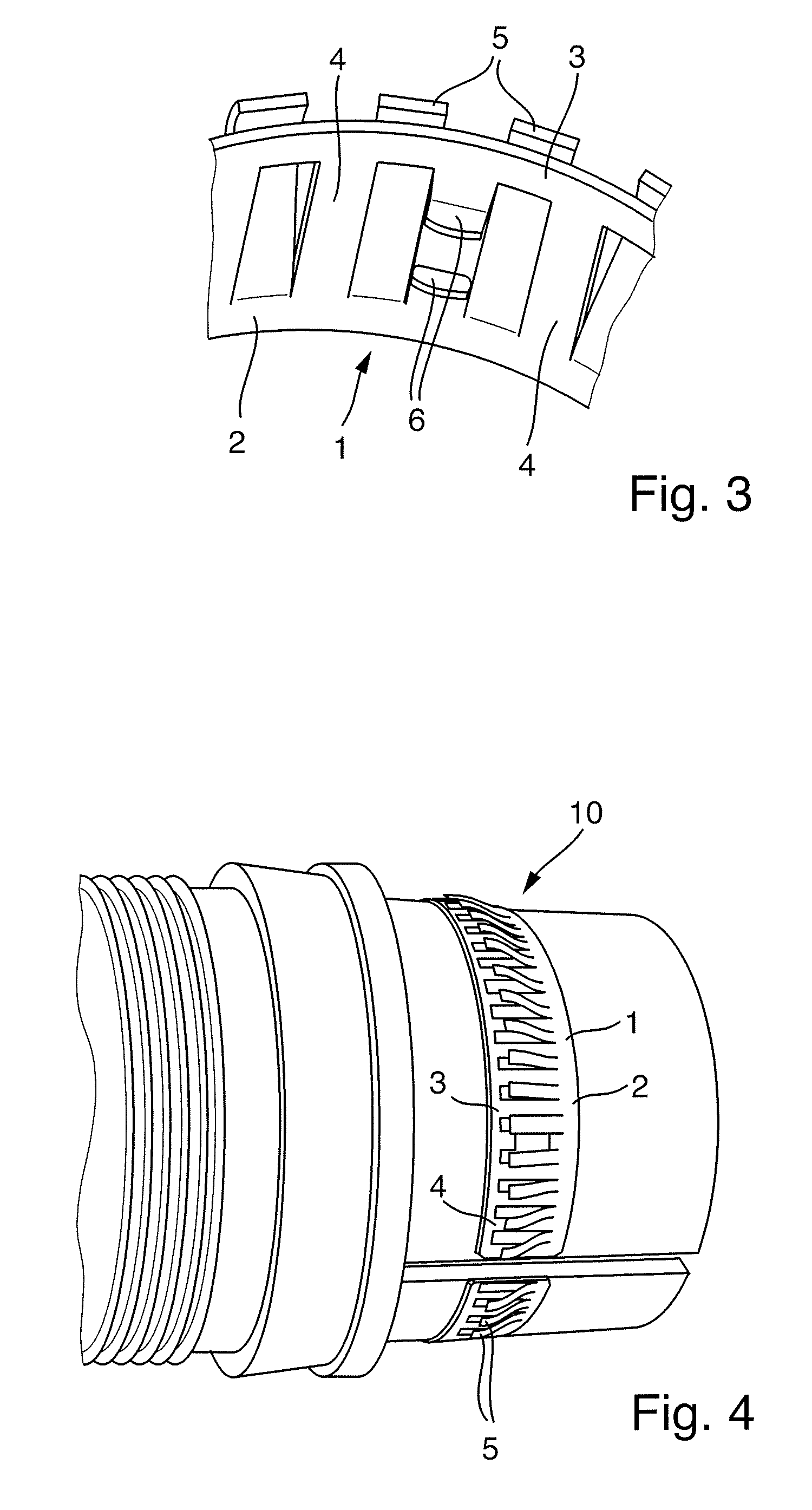
[0020]FIGS. 1 to 4 show an exemplary embodiment of a grounding finger for shielding an electrical plug connection according to aspects of the invention. The grounding finger 10 in this case has a ring shape which is open on one side and comprises a sleeve-like support element 1 which is provided with a slot 7 on one side. The support element 1 has a first outer edge 2 and also a second outer edge 3 which is situated opposite said first outer edge. The edges 2, 3 are firmly connected to one another by means of connecting webs 4. The sleeve-like support element 1 in this case has an approximately rectangular shape which is bent into the annular shape, which is opened by means of a slot 7, in accordance with a predefined diameter. In the exemplary embodiment which is shown in the figures, connecting webs 4 and outwardly protruding spring limbs 5 are provided alternately in each case. The spring limbs 5 are produced from the originally flat, rectangular support element 1 by means of pun...


PUM


Abstract

Grounding finger for shielding at an electrical connection between a plug connector and a mating plug connector of an electrical line, having a sleeve-like support element which has a first outer edge and a second outer edge, axial connecting webs being provided between the outer edges, and having a plurality of spring limbs which act radially outward and, at least at one end, are connected to one of the edges in order to generate a spring-loaded contact force to the outer plug connector, with some of the connecting webs being interrupted and being formed in each case with at least one contact lug which faces radially inward.

Description

CROSS-REFERENCE TO RELATED APPLICATION[0001]This application claims priority to German Patent Application No. 10 2014 210 254.5, filed May 28, 2014, which is incorporated by reference herein in its entirety.FIELD OF THE INVENTION[0002]The present invention relates to shielding of electrical plug connectors, more precisely to a grounding finger for such shielding of plug connectors in electrical lines.BACKGROUND OF THE INVENTION[0003]In order to ensure continuous shielding of electrical lines across the plug connectors too, it is necessary for an element which shields against interference signals from the electrical line or from outside the electrical line to be provided at the position of the plug connectors and mating plug connectors. By way of example, so-called grounding fingers, which establish a releasable connection but allow secure continuous shielding of the line in the closed state, are inserted between the plugs and mating plugs for this purpose in the case of plug connect...

Claims


Application Information

Patent Timeline
Patent Type & Authority Patents(United States)
IPC IPC(8): H01R13/17H01R13/6583H01R13/18H01R4/48
CPCH01R4/4881H01R13/18H01R13/6583H01R13/17
Inventor SINGER, HELMUTLITTEK, MARTINSTANDFEST, ANDREAS
Owner ITT MFG ENTERPRISES LLC
Why Eureka
Try Eureka