
Balancing method of tunable duplexer

a balancing method and duplexer technology, applied in the direction of transmission, electrical equipment, etc., can solve the problems of large physical components and high cost of duplex filters, and achieve the effect of improving balancing

Active Publication Date: 2016-06-21
AVAGO TECH INT SALES PTE LTD
View PDF6 Cites 9 Cited by
  • Summary
  • Abstract
  • Description
  • Claims
  • Application Information

AI Technical Summary

Benefits of technology

[0019]According to an embodiment of the invention, an advantage is achieved that adequate balance of a tunable duplexer is obtained before a high power TX signal is injected to an input of the tunable duplexer, which results in more time for fine tuning the balance and protects RX circuitry from high power TX signal.

Problems solved by technology

The duplex filters are expensive and physically large components.

Method used


Image

  • Balancing method of tunable duplexer
  • Balancing method of tunable duplexer
  • Balancing method of tunable duplexer

Examples


Embodiment Construction

[0030]Generally, references to certain standards, media and / or resources in this description are rather supposed to be exemplary for the purpose of illustration in order to improve the ease of understanding of the invention. They are not to be understood as limiting the inventive concept. Likewise, the language as well as terms used herein, such as e. g. signal names, device names and the like, are to demonstrate the embodiments only. Use of such language or terms apart from their understanding according to this disclosure shall not be applied to the invention for the purpose of limiting its scope.

[0031]Generally, mobile devices may be user equipments (UE) such as cellular phones, smart phones, laptop's, handhelds, tablets, vehicles, machines, or special purpose means with a wireless connection to a communication counterpart, or the like. A mobile device may also be a module, a modem on module, a system in package or a system on chip which can be connected to or inserted in a user e...


PUM


Abstract

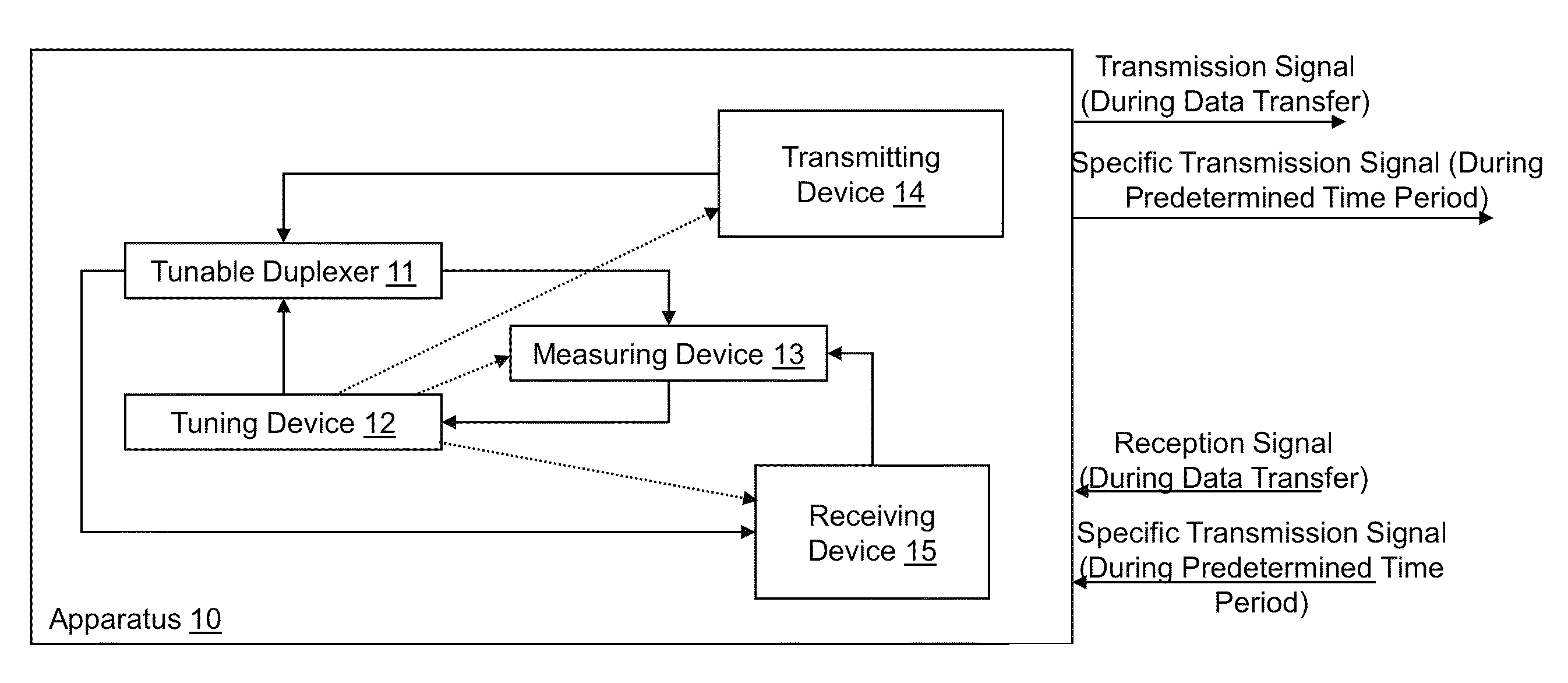
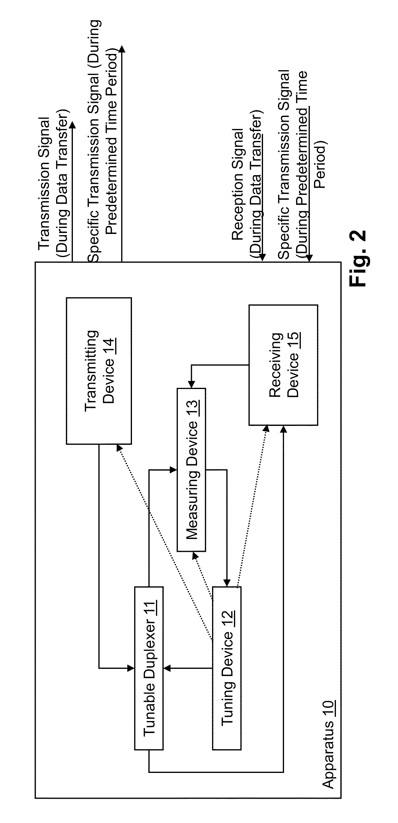
An apparatus comprises a tunable duplexer configured to output a transmission signal to be wirelessly transmitted from the apparatus at a transmission frequency, and configured to input a reception signal wirelessly received by the apparatus at a reception frequency, a tuning device connected to the tunable duplexer, configured to control a balance between impedances of an antenna port and of a balance port of the tunable duplexer, a transmitting device configured to, during a predetermined time period, wirelessly transmit a specific transmission signal for calibration of the tunable duplexer, a receiving device configured to, during the predetermined time period, wirelessly receive the specific transmission signal transmitted by the transmitting device, and a measuring device configured to, during the predetermined time period, measure the power of the specific transmission signal received by the receiving device. The tuning device controls the balance based on the measured power of the specific transmission signal.

Description

BACKGROUND OF THE INVENTION[0001]1. Field of the Invention[0002]The present invention relates to a balancing method of a tunable duplexer usable e.g. in a multimode cellular transceiver. For example, an embodiment of the present invention is applicable to a 3GPP communication system.[0003]2. Related Background Art[0004]Prior art which is related to this technical field can e.g. be found in:[0005][1] Mikhemar, Darabi, Abidi: “A Multiband RF Antenna Duplexer on CMOS: Design and Performance”, http: / / ieeexplore.ieee.org / stamp / stamp.jsp?arnumber=6544685[0006][2] Abdelhalem, Gudem, Larson: “A tunable differential duplexer in 90 nm CMOS”, http: / / ieeexplore.ieee.org / stamp / stamp.jsp?tp=&arnumber=6242241[0007][3] US 2011 / 299436 A1[0008][4] US 2011 / 299435 A1[0009][5] US 2011 / 300814 A1[0010][6] US 2011 / 053539 A1[0011]The following meanings for the abbreviations used in this specification apply:3GPP third generation partnership projectADC analog-digital converterBS base stationCMRR common mode r...

Claims


Application Information

Patent Timeline
Patent Type & Authority Patents(United States)
IPC IPC(8): H04B1/40H04B1/54H04B1/525H04B1/04H04B1/18
CPCH04B1/54H04B1/525H04B1/0458H04B1/18
Inventor LEHTINEN, TEIJO HENRIKKIIMMONEN, ANTTI OSKARI
Owner AVAGO TECH INT SALES PTE LTD
Learn More