
Joystick, system and method for manouvering a boat

a joystick and boat technology, applied in the field of boat manoeuvring joystick, can solve the problems of cumbersome docking operation and drifting of the stern of the boat from the quay, and achieve the effect of easing the docking of the boa

Active Publication Date: 2016-07-12
SLEIPNER MOTOR AS
View PDF12 Cites 15 Cited by
  • Summary
  • Abstract
  • Description
  • Claims
  • Application Information

AI Technical Summary

Benefits of technology

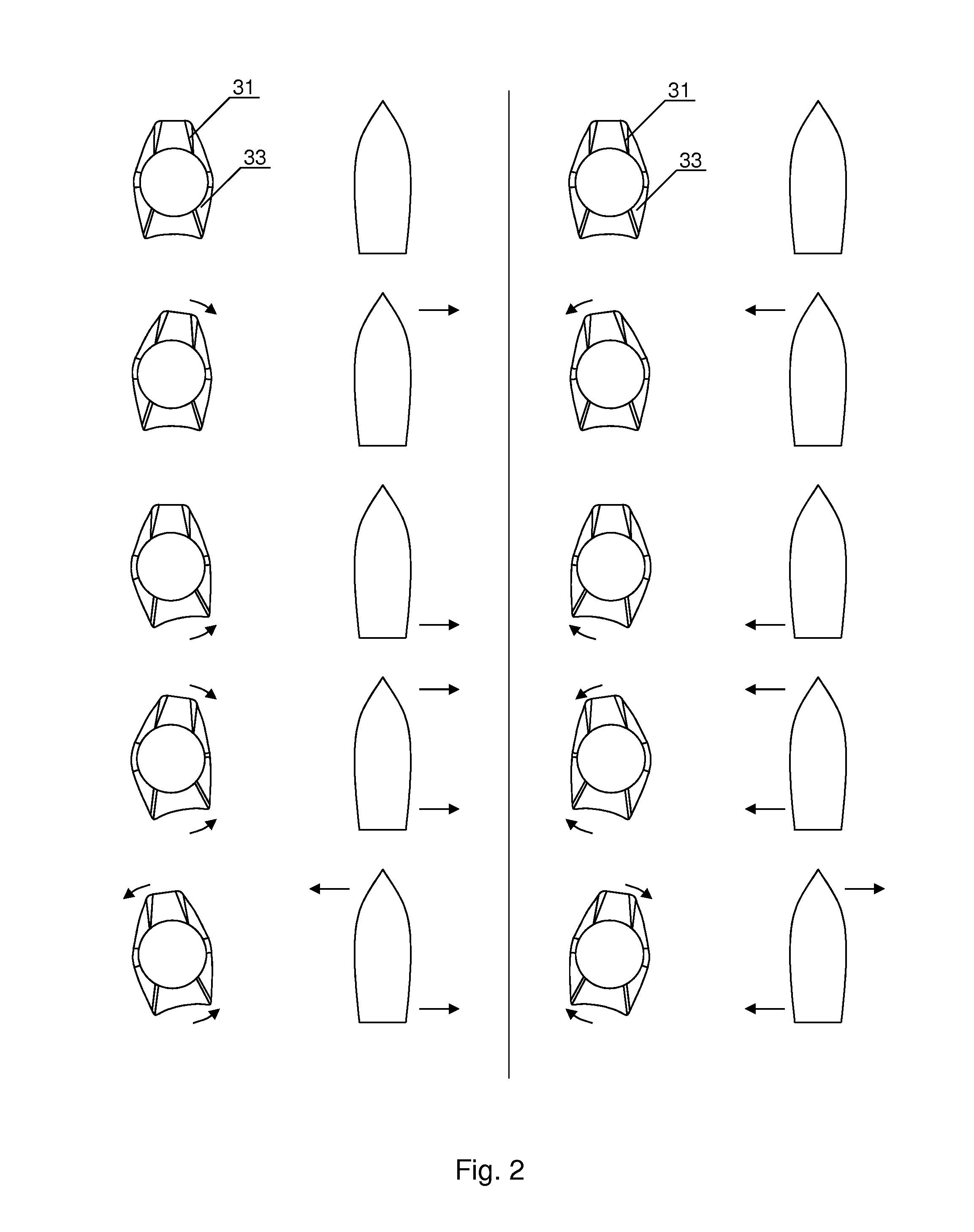
[0070]In addition, it is shown that the second bidirectional control knob (33) is pushed in the starboard direction. This will result in additional stern force (F2) acting on the stern of the boat towards starboard. It should be noted that the stern force (F2) in this case will result in the stern part of the boat be pulled in the starboard direction. This is different from control systems according to background art where the stick can be rotated, resulting in a rotational movement about the centre of the boat, i.e. the bow in this case would be pulled in the port direction. The additional flexibility of the manoeuvring system (1) according to the invention has the advantage that the docking operation can be performed more accurate. In FIG. 3 a quay, or landing stage (Q) is shown for illustration. The bow of the boat is already perfectly close to the quay, and the only remaining action is to line up the stern with the quay as well. By pushing the second bidirectional control knob (33) this can easily be achieved with the present invention. On the contrary, a rotation of the boat would certainly align it with the quay, but also remove it from the quay, and an additional right force is necessary to take it back to the quay. The advantage of the invention can be even better understood by considering that a local wind or current is acting on the stern of the boat in the port direction, and that the stern force (F2) can compensate for the drift of the stern. Local wind or current can be e.g. due to obstacles nearby that shields the bow of the boat.
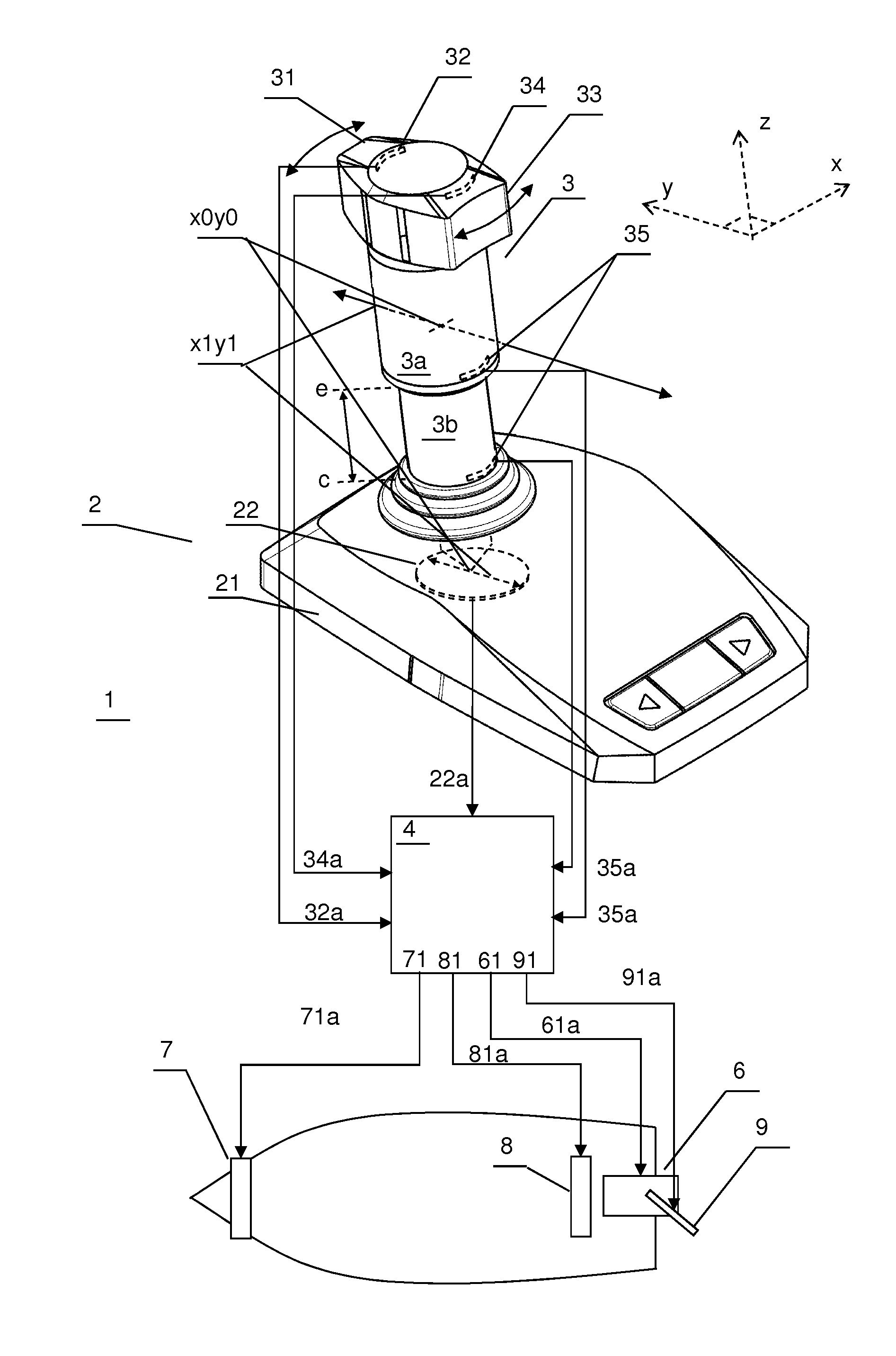
[0071]According to an embodiment the boat manoeuvring system (1) in combination with any of the elements described above, comprises a manoeuvring stick (3) comprising an outer shaft element (3a) and an inner shaft element (3b) telescopically arranged relative each other, wherein the manoeuvring stick (3) is arranged to expand telescopically from a collapsed position (c) to an extended position (e) when the outer shaft element (3a) is lifted relative the base (21), and to collapse telescopically from the extended position (e) to the collapsed position (c) when the outer shaft element (3a) is lowered relative the base (21),
[0072]the manoeuvring stick (3) further comprising one or more mode sensors (35) arranged for detecting whether the manoeuvring stick (3) is in the collapsed position (c) or the elongated position (e), wherein
[0073]the manoeuvring control unit (4) is further arranged for receiving mode control signals (35a) from said mode sensors (35) for calculating a propulsion signal (61a) indicating a larger propulsion force when the mode control signals (35a) indicate that the manoeuvring stick (3) is in the elongated position (e) than when the mode control signals (35a) indicate that the manoeuvring stick (3) is in the collapsed position (c), when the manoeuvring stick is in a position (x1y1) different from the zero position (x0y0).
[0074]Thus, the invention is in an embodiment a method for manoeuvring a boat with a boat manoeuvring joystick (2) as described above. The method comprises repeating the following steps one or more times;
[0075]in a first docking operation, operating the manoeuvring stick (3) by moving it in forward, backward, port and starboard directions to position the boat close to a quay,

Problems solved by technology

One of the problems related to the prior art described above, where the boat pivots around its main vertical axis as a response to the twist of the stick, is that the docking operation may in certain situations become cumbersome.
If, for instance there is a local wind blowing, or a local current, as may be the case where there are obstacles close to the quay, the stern of the boat may drift away from the quay during docking.

Method used


Image

  • Joystick, system and method for manouvering a boat
  • Joystick, system and method for manouvering a boat
  • Joystick, system and method for manouvering a boat

Examples


Embodiment Construction

[0041]With reference to the attached drawings the device and system according to the invention will now be explained in more detail.

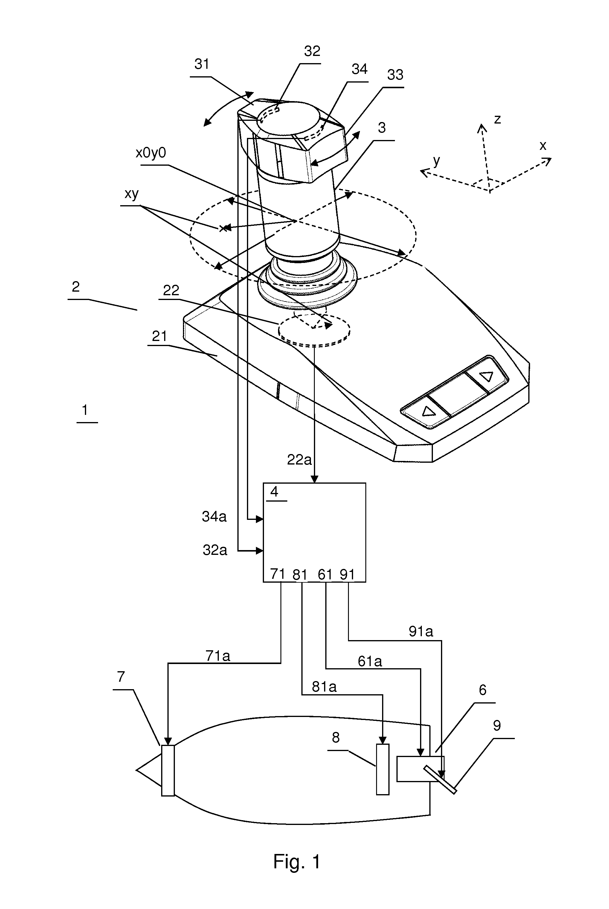
[0042]FIG. 1 illustrates in the upper part a boat manoeuvring joystick (2), according to an embodiment of the invention. In combination with the manoeuvring control unit (4) the boat manoeuvring system (1), also according to the invention, can be seen in the same figure. The lower part of the figure illustrates how the system may be connected to thrusters, propulsion devices and rudders of a boat or a vessel.

[0043]For the description of the different embodiments, the following definitions related to directions used have been defined. The boat manoeuvring joystick (2) has a forward, or fore direction defined as (y) in the drawings. This corresponds to the forward direction of the boat. The backward, or aft direction is opposite the forward direction. Lateral directions are lateral to the forward direction and in the direction of the (x) axis in the drawi...


PUM


Abstract

A boat maneuvering joystick, system and method for maneuvering a boat. The joystick has a base with sensors arranged for detecting a position of the maneuvering stick. The maneuvering stick comprises a first bidirectional control knob and a second bidirectional control knob, arranged movably relative each other. The joystick comprises first control sensors detecting a first position of the first bidirectional control knob and second control sensors detecting a second position of the stern control knob. The system comprises a maneuvering control unit comprising a bow thruster output terminal and a propulsion output terminal. The maneuvering control unit is arranged for receiving position, first and second control signals and calculating a bow thruster signal and a propulsion signal. A dual mode joystick is also shown.

Description

CROSS REFERENCE TO RELATED APPLICATIONS[0001]This application is the National Phase of PCT International Application No. PCT / NO2013 / 050150, filed on Sep. 5, 2013, which claims priority under 35 U.S.C. 119(e) to U.S. Provisional Application No. 61 / 697,548, filed on Sep. 6, 2012 and under 35 U.S.C. 119(a) to Patent Application No. 12006297.1, filed in Europe on Sep. 6, 2012, all of which are hereby expressly incorporated by reference into the present application.FIELD OF THE INVENTION[0002]The present invention relates to the field of watercraft manoeuvring, such as manoeuvring of vessels and boats. More particularly it relates to a boat manoeuvring joystick, a boat manoeuvring system and a method for manoeuvring a boat.BACKGROUND OF THE INVENTION[0003]Traditionally docking of watercrafts has been one of the more critical and difficult tasks to perform for a seaman. Especially when the weather conditions are harsh and the watercrafts or boats are relatively large.[0004]A number of sys...

Claims


Application Information

Patent Timeline
Patent Type & Authority Patents(United States)
IPC IPC(8): B63H25/02G05G9/047B63H21/21B63H25/42
CPCB63H25/02B63H21/21B63H21/213B63H25/42G05G9/047B63H2025/026
Inventor SKAUEN, RONNY
Owner SLEIPNER MOTOR AS
Learn More