
Light-guide device having a plurality of light-guide elements for a vehicle control panel

a technology of light-guide devices and control panels, which is applied in the direction of instruments, indication devices, transportation and packaging, etc., can solve the problems of long time for the quality control of the instrument panel itself, long mounting time, and long time for the instrument panel itself. achieve the effect of simple and cost-effectiv

Active Publication Date: 2016-07-12
MARELLI EURO SPA
View PDF17 Cites 5 Cited by
  • Summary
  • Abstract
  • Description
  • Claims
  • Application Information

AI Technical Summary

Benefits of technology

[0010]It is the object of the present invention to provide a light-guide device designed to light a plurality of indicators in a vehicle control panel, which allows the above problem to be solved in a simple and cost-effective manner.
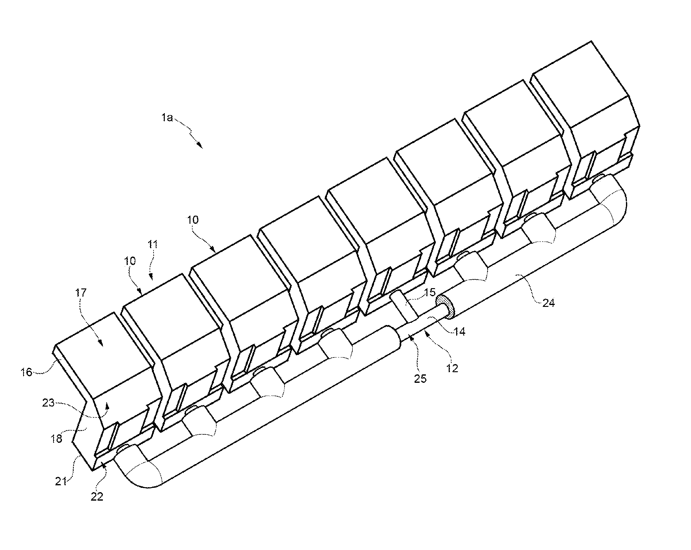
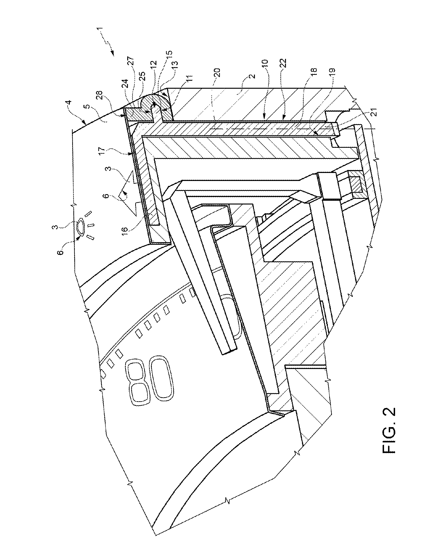
[0011]Accordingly, the present invention is directed toward a light-guide device including a body made as a single piece and having a plurality of light-guide elements. Each of the light-guide elements includes respective lighting portions for lighting respective indicators in a control panel and respective transmission portions for guiding respective light beams toward the lighting portions. In addition, the body also includes at least one supporting element which joins the light guide elements to one another. An opaque coating adheres onto the outer surface 25 of the support element and acts to absorb the light exiting, in use, from the light-guide elements in the supporting element so as to prevent light transmission in said supporting element from each of the light guide elements to the adjacent light-guide elements.

Problems solved by technology

However, since they are separate pieces, they still require a long mounting time when assembling the instrument panel and a long time for the quality control of the instrument panel itself.
However, the modes indicated in WO2006041876A1 for reducing the light leaking through the lens are not satisfactory.

Method used


Image

  • Light-guide device having a plurality of light-guide elements for a vehicle control panel
  • Light-guide device having a plurality of light-guide elements for a vehicle control panel
  • Light-guide device having a plurality of light-guide elements for a vehicle control panel

Examples


Embodiment Construction

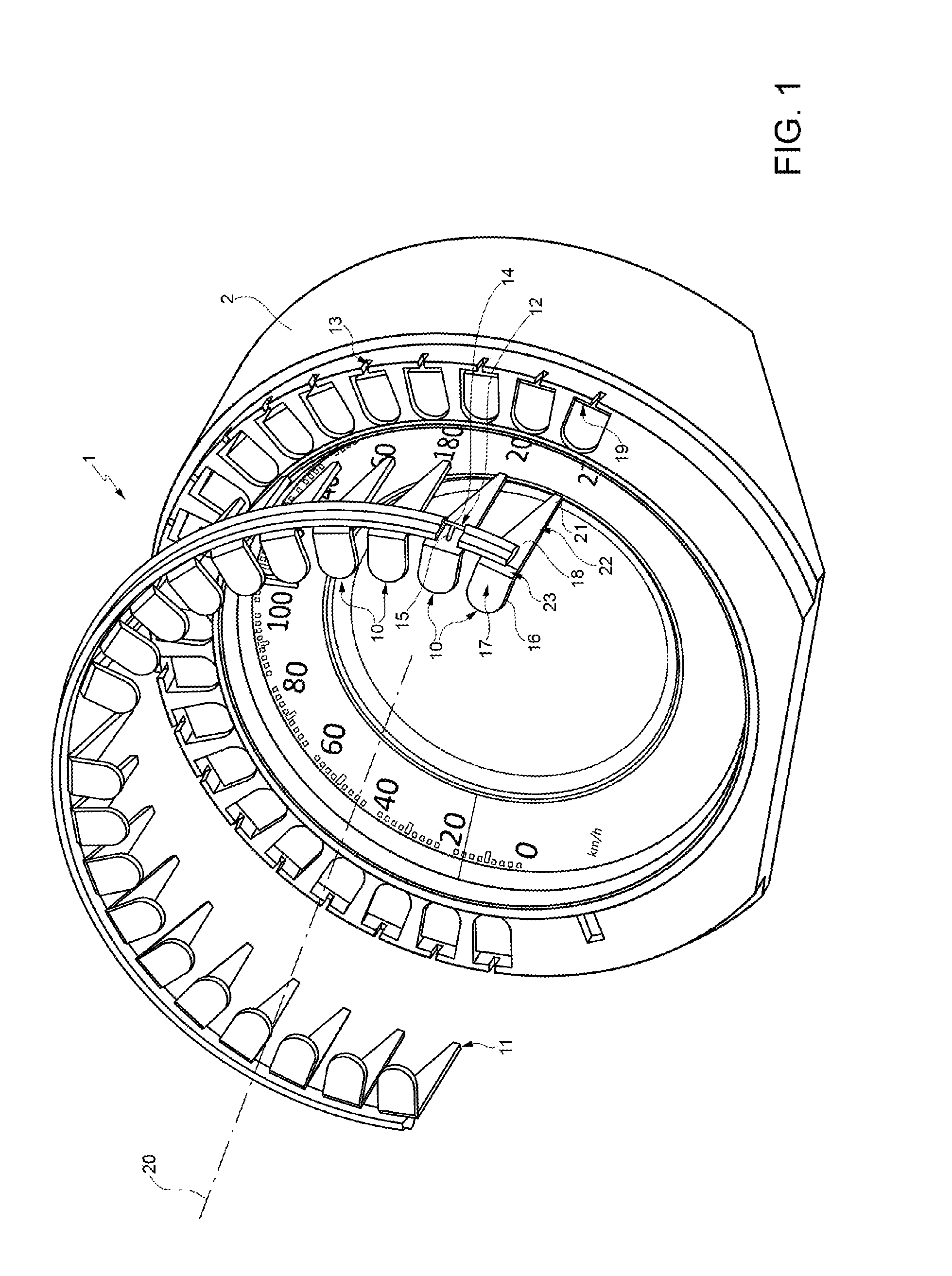
[0017]In FIG. 1, reference numeral 1 indicates, as a whole, a light-guide device (partially shown) belonging to a control panel 2, in particular an instrument panel of a vehicle.

[0018]As seen in FIG. 2, the control panel 2 includes a plurality of indicators 3, which are defined by warning lights, graduated scales, numbers, etc. for providing information about the operation of respective devices and / or about the activation / deactivation of respective operating functions. In particular, a part of indicators 3 is carried by a plate 4, which substantially extends with a circle arc shape about the rotation axis of a finger. Plate 4 comprises an opaque main portion 5, i.e. non-permeable to light or light-blocking, and a plurality of windows 6, which are made of a light permeable material or as through openings in portion 5 and have a profile shaped so as to define the above indicators 3.

[0019]The control panel 2 further includes a plurality of light sources (not shown in the accompanying f...


PUM


Abstract

A light-guide device has a single piece body including a plurality of light guiding elements joined together by at least one supporting element. An opaque coating is provided on an outer surface of the at least one supporting element, to absorb the light entering into the supporting element from the light-guide elements.

Description

REFERENCE TO RELATED APPLICATION[0001]This application is based upon and claims priority to Italian Patent Application BO2012A 00070 filed on Aug. 6, 2012.BACKGROUND OF INVENTION[0002]1. Field of Invention[0003]The present invention relates to a light-guide device designed to light a plurality of indicators in a vehicle control panel. In particular, the present invention relates to a light-guide device of an instrument panel in a motor vehicle or motorcycle.[0004]2. Description of Related Art[0005]As known, vehicles have an instrument panel provided with a plurality of indicators, which are defined by graduated scales, warning lights, numbers, etc. and are lighted and / or turned off for providing information about the operation of devices and / or the activation / deactivation of vehicle functions.[0006]Each of such indicators receives light from a corresponding light source independently of the other indicators. The light sources are usually arranged in a position spaced apart from the ...

Claims


Application Information

Patent Timeline
Patent Type & Authority Patents(United States)
IPC IPC(8): G02B6/10B60K37/02G01D13/00G01D11/28
CPCG01D13/00B60K37/02G01D11/28B60K2350/203B60K2350/402B60K2370/336B60K2370/341B60K2370/33B60K2370/695
Inventor MOUARD, SYLVAINMASALA, LUCARAMELLA, ANDREA
Owner MARELLI EURO SPA
Learn More