Low power radar level gauge system

a low-power, radar-based technology, applied in the direction of instruments, machines/engines, using reradiation, etc., can solve the problems of increased sweep time, less suitable for applications where the power (and/or energy) is not suitable, and the integrated microwave circuit is not suited to the desired application, etc., to achieve accurate filling level determination, reduce cost, and limited supply of energy and/or power

Active Publication Date: 2016-07-12
ROSEMOUNT TANK RADAR
View PDF32 Cites 13 Cited by
  • Summary
  • Abstract
  • Description
  • Claims
  • Application Information

AI Technical Summary

Benefits of technology

[0007]In view of the above, a general object of the present invention is to provide for an improved radar level gauge system enabling accurate filling level determination for applications with severely limited supply of energy and / or power. It is a further object of embodiments of the present invention to achieve this at a lower cost than with currently available radar level gauge systems of the FMCW-type.

Problems solved by technology

Although highly accurate, conventional FMCW systems—continuous as well as stepped—are relatively power hungry, which makes them less suitable for applications where the power (and / or energy) is limited.
For applications with limited available energy and / or power, also the cost and size of a level measuring system are often crucial parameters.
It would therefore appear that integrated microwave circuits are not suited for the desired applications, where energy / power is scarce.
Tests and theoretical calculations show that a sweep duration of about 10 ms should be sufficiently short to fulfill the energy / power consumption criteria for a two-wire current loop system, which is currently seen as the most challenging application.
However, as the sampling frequency is fixed at a reasonable value from an A / D conversion standpoint, any increase of the number of samples will inevitably lead to an increased sweep time.
For a given measurement range, there is thus a tradeoff between resolution (bandwidth) on the one hand, and power consumption (sweep time) on the other.

Method used


Image

  • Low power radar level gauge system
  • Low power radar level gauge system
  • Low power radar level gauge system

Examples


first embodiment

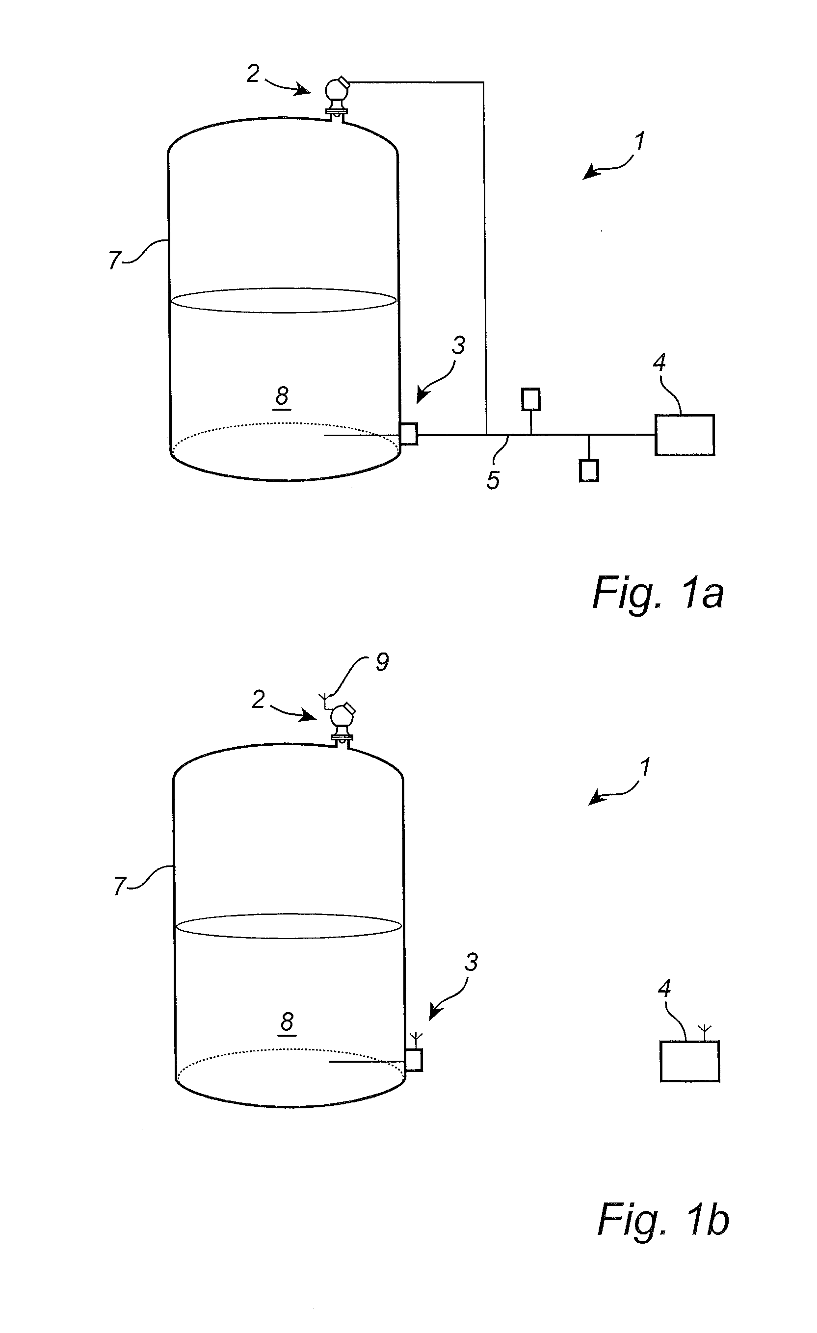
[0070]FIG. 1a schematically shows a process monitoring system 1 comprising a plurality of field devices, including a radar level gauge system 2 and a temperature sensing device 3 connected to a host system 4 through a communication line 5 in the form of a 4-20 mA current loop. Further field devices connected to the communication line 5 are schematically indicated as boxes.

[0071]The radar level gauge system 2 and the temperature sensor 3 are both arranged on a tank containing a product 8 to be gauged.

[0072]In addition to providing signals on the current loop, typically in the form of a current value being indicative of a measurement value, the field devices may be powered using the current provided by the current loop 5. As has been previously discussed further above in the Background and Summary sections, this severely limits the power that is available for operation of the field devices, in particular for active field devices, such as the radar level gauge system 2 in FIG. 1a.
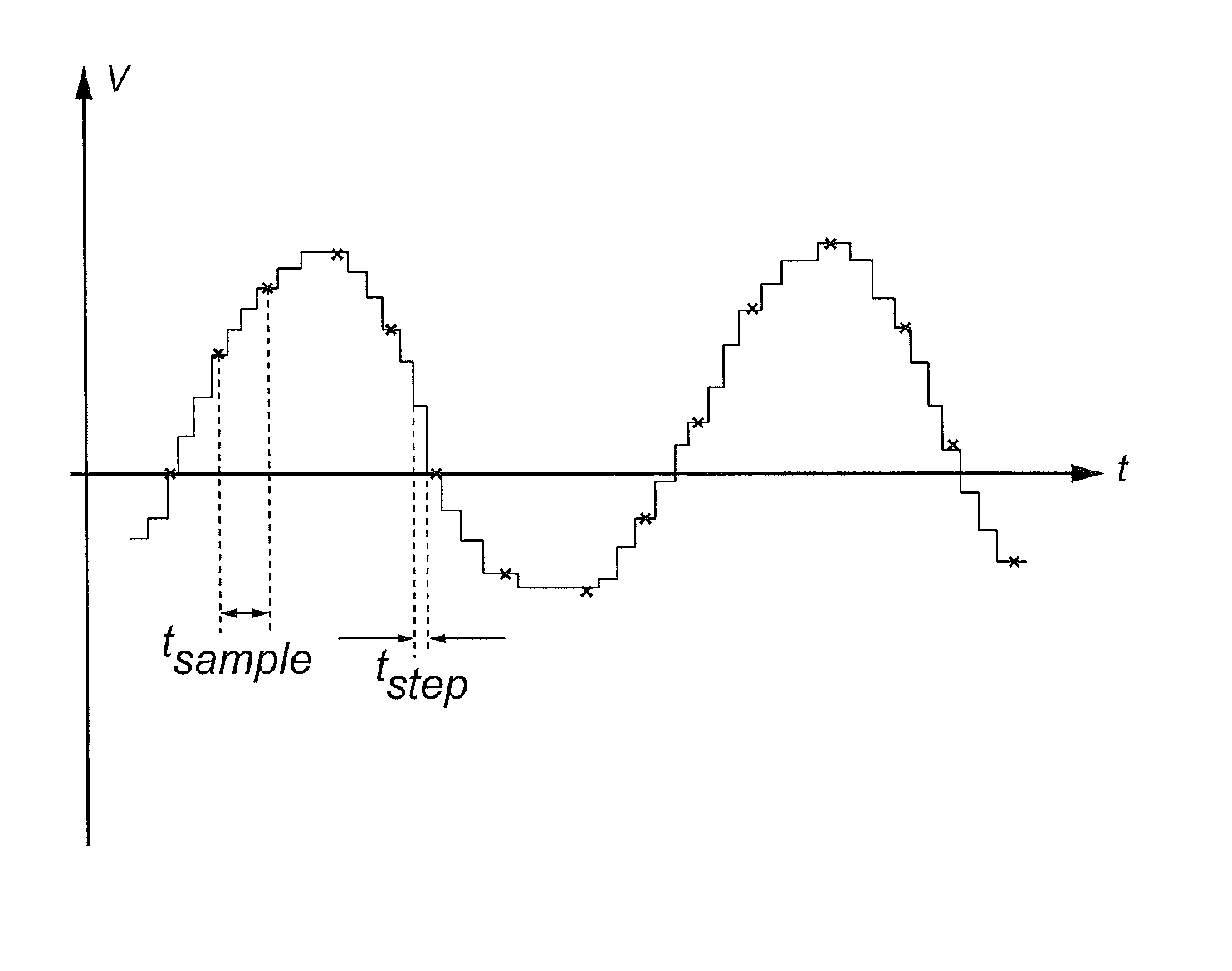
[007...

second embodiment

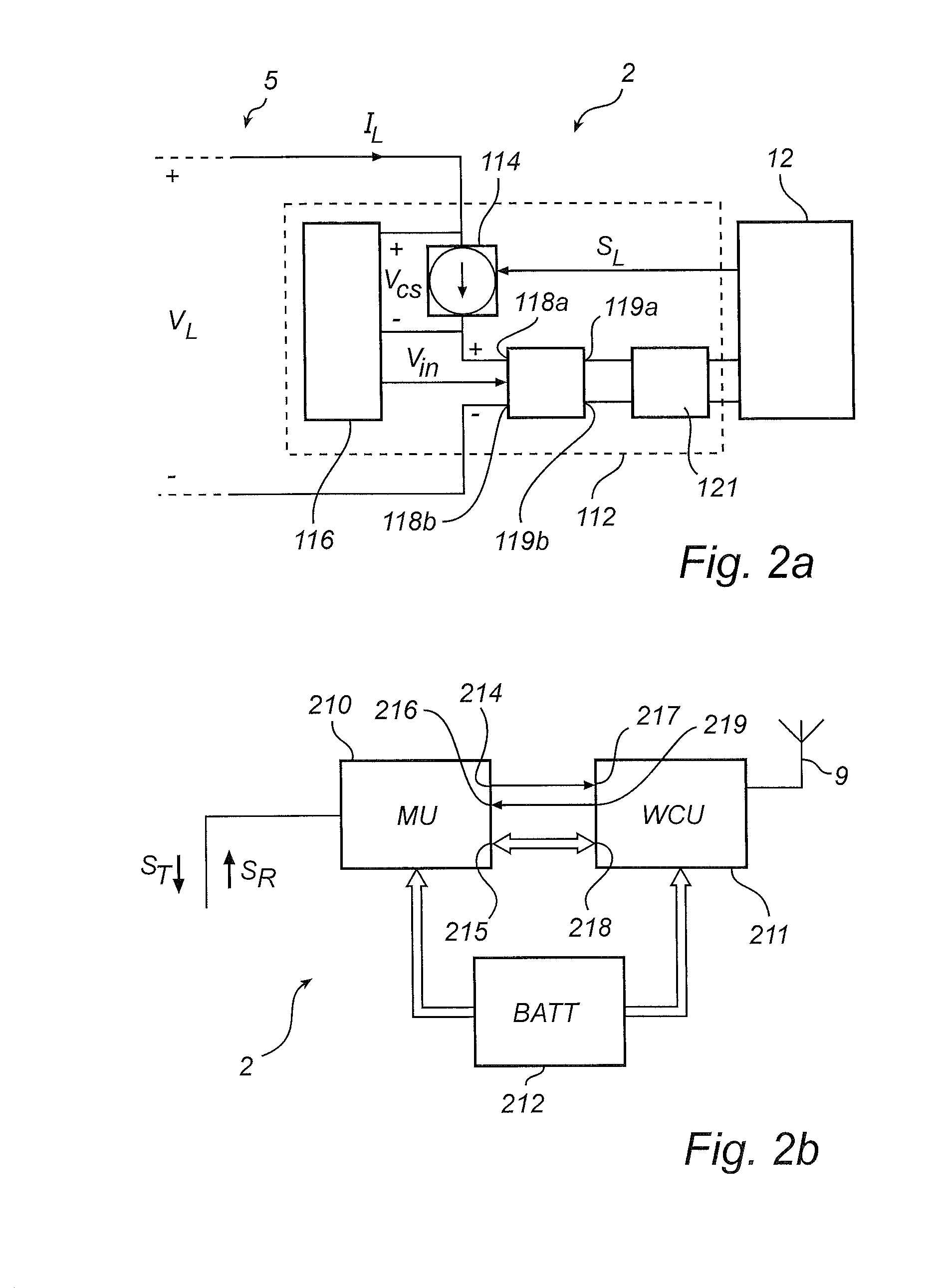
[0087]With reference to FIG. 2b, the radar level gauge system 2 in FIG. 1b comprises a measurement unit (MU) 210, a wireless communication unit (WCU) 211 and a local energy store in the form of a battery 212. The wireless communication unit 211 may advantageously be compliant with WirelessHART (IEC 62591).

[0088]As is schematically indicated in FIG. 2b, the measurement unit 210 comprises a first output 214, a second output 215, and a first input 216. The first output 214 is connected to a first input 217 of the wireless communication unit 211 through a first dedicated discreet line, the second output 215 is connected to a second input 218 of the wireless communication unit 211, and the first input 216 is connected to a first output 219 of the wireless communication unit 211 through a second dedicated discreet line. The second output 215 of the measurement unit 210 and the second input 218 of the wireless communication unit 211 may be configured to handle bidirectional data communicat...


PUM


Abstract

The present invention relates to a radar level gauge system comprising a signal propagation device; a microwave signal source; a microwave signal source controller; a mixer configured to combine a transmit signal from the microwave signal source and a reflection signal from the surface to form an intermediate frequency signal; and processing circuitry coupled to the mixer and configured to determine the filling level based on the intermediate frequency signal.

Description

TECHNICAL FIELD OF THE INVENTION[0001]The present invention relates to a radar level gauge system, and to a method of determining a filling level of a product in a tank.TECHNICAL BACKGROUND[0002]Since radar level gauging was commercialized in the 1970's and 1980's, frequency modulated continuous wave (FMCW) gauging has been the dominating measuring principle for high accuracy applications. An FMCW-type filling level measurement comprises transmitting into the tank a signal which is swept over a frequency range in the order of a few GHz. For example, the signal can be in the range 24-27 GHz, or 9-10.5 GHz. The transmitted signal is reflected by the surface of the product in the tank (or by any other impedance transition) and an echo signal, which has been delayed a certain time, is returned to the gauge. The echo signal is combined with the transmitted signal in a mixer to generate a combined signal, having a frequency equal to the frequency change of the transmitted signal that has ...

Claims


Application Information

Patent Timeline
Patent Type & Authority Patents(United States)
IPC IPC(8): G01F23/284G01S13/08G01S13/88G01S7/35G01S13/34G01S7/00G01S7/02
CPCG01F23/284G01S7/35G01S13/08G01S13/343G01S13/88G01S7/003G01S2007/027G01S7/027
Inventor JIRSKOG, ANDERSKLEMAN, MIKAELLARSSON, LARS OVE
Owner ROSEMOUNT TANK RADAR
Why Eureka
Try Eureka