Variable directivity electret condenser microphone

a condenser microphone and variable directivity technology, applied in the field of condenser microphones, can solve the problems of inevitability of increasing the cost and the complexity of the circuit configuration, and achieve the effect of simplifying the circuit configuration

Inactive Publication Date: 2016-07-12
AUDIO-TECHNICA
View PDF5 Cites 0 Cited by
  • Summary
  • Abstract
  • Description
  • Claims
  • Application Information

AI Technical Summary

Benefits of technology

[0018]An objective of the present invention is to provide a variable directivity electret condenser microphone that overcomes the above-described problems of the electret condenser microphone that varies directivity by arranging two microphone units in front and back in a back to back manner, and which outputs an audio signal in a balanced manner.
[0029]Therefore, the variable directivity electret condenser microphone according to the present invention does not need a special circuit configuration such as a phase inverting amplifier, and can simplify the circuit configuration, compared with the example disclosed in JP 2012-65147 A described above.
[0030]Further, the variable directivity electret condenser microphone according to the present invention can overcome the problem of occurrence of noise due to vibration caused by employment of a variable-capacity capacitor (variable capacitor), and can contribute to the simplification of the circuit configuration, compared with the example disclosed in JP 2008-118260 A described above.

Problems solved by technology

According to the above configuration, it is also necessary to include an auxiliary configuration of the above-described DC-DC converter and the like in the condenser microphone units, and thus it is inevitable to have an increase in the cost.
Therefore, employment of the phase adjustment means has a problem of complexity of a circuit configuration, and thus there is room for improvement.
Therefore, an electrostatic capacity is changed when external vibration is added to the variable-capacity capacitor, and this becomes a cause of occurrence of noise.

Method used


Image

  • Variable directivity electret condenser microphone
  • Variable directivity electret condenser microphone
  • Variable directivity electret condenser microphone

Examples


second embodiment

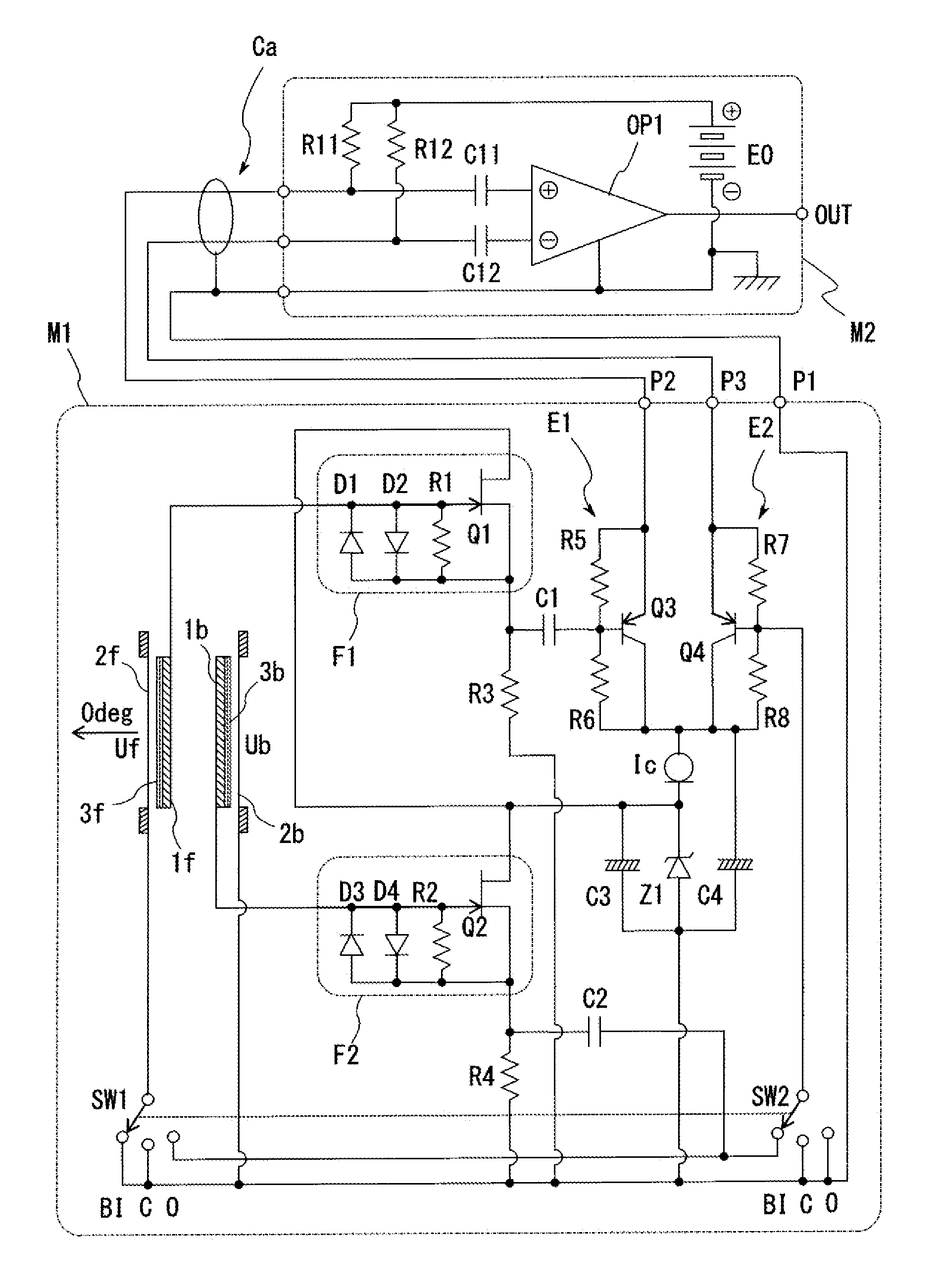
[0074]FIG. 5 illustrates a variable directivity electret condenser microphone according to the present invention, and FIG. 5 illustrates principal parts only, which are alternative to the variable directivity electret condenser microphone M1 described based on FIG. 1.

[0075]In the example illustrated in FIG. 5, a first fixed electrode 1f and a first diaphragm 2f in a front-side unit Uf are mutually switched and connected, and a second fixed electrode 1b and a second diaphragm 2b in a back-side unit Ub are also mutually switched and connected, with respect to the example illustrated in FIG. 1.

[0076]That is, the first diaphragm 2f that configures the front-side unit Uf is connected to an input terminal of a first impedance converter F1, and the first fixed electrode 1f is connected to a movable contact of a first switch SW1. Further, the second diaphragm 2b that configures the back-side unit Ub is connected to an input terminal of a second impedance converter F2, and the second fixed e...

first embodiment

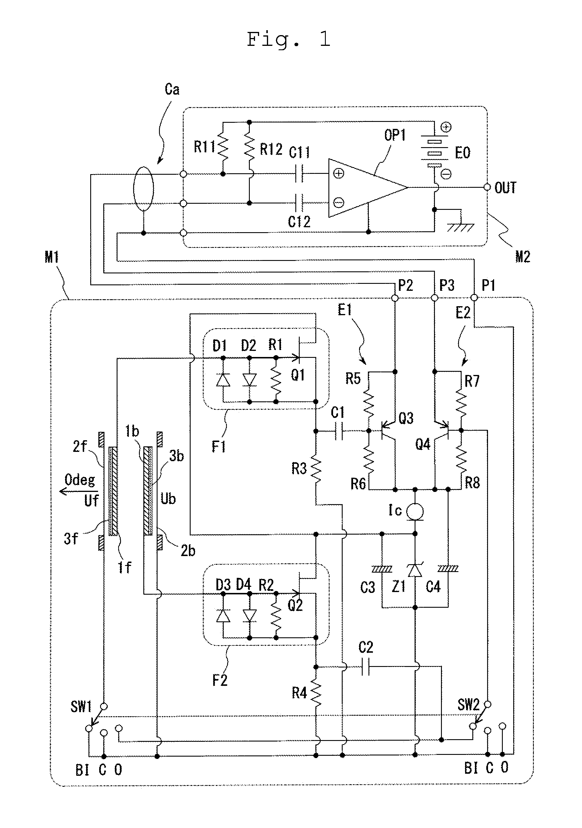
[0079]That is, FIGS. 6 to 8 correspond to the equivalent circuit diagrams in the first embodiment illustrated in FIGS. 2 to 4, described above.

[0080]In the second embodiment illustrated in FIG. 5, when the directivity variable switches select BI that is a first directivity mode, an input terminal of a second buffer circuit E2 is connected to an output terminal of the second impedance converter F2, as illustrated in FIG. 6.

[0081]Accordingly, signals of the polar patterns illustrated in FIG. 6 are respectively supplied to a second terminal pin P2 and a third terminal pin P3, and are subtracted in a subtraction circuit OP1 of the mixer M2. As a result, an audio signal having the bidirectivity can be obtained.

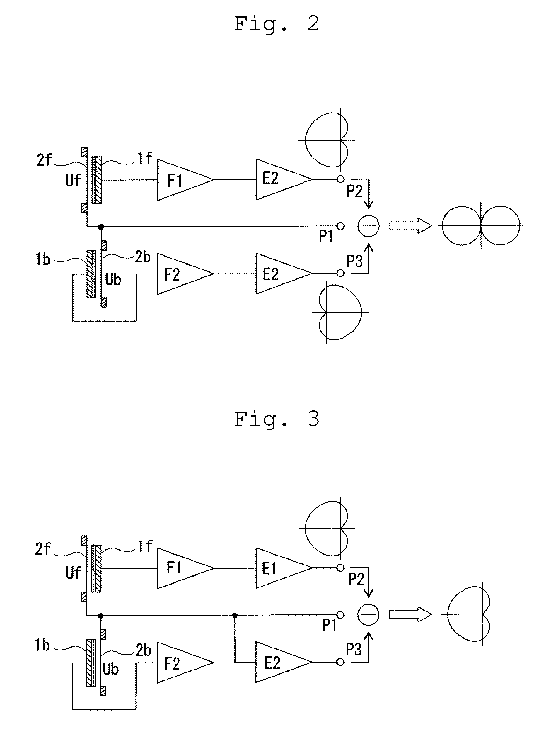
[0082]Next, when the directivity variable switches select the unidirectivity C that is a second directivity mode, the input terminal of the second buffer circuit E2 is grounded, as illustrated in FIG. 7.

[0083]Accordingly, while a signal of the polar pattern illustrated in the drawi...


PUM


Abstract

Provided is a variable directivity electret condenser microphone that can simplify a circuit configuration, and outputs an audio signal in a balanced manner, which includes electrically independent first and second electret condenser microphone units in which first and second fixed electrodes are arranged back to back and facing each other in a mutually non-conductive state, and first and second diaphragms are arranged facing the first and second fixed electrodes with fixed intervals therefrom respectively, a first impedance converter having an input terminal connected to the first fixed electrode, and a first buffer circuit connected to the first impedance converter, a second impedance converter having an input terminal connected to the second fixed electrode, and a second buffer circuit selectively connected to the second impedance converter, and a directivity variable switch that can alternatively select a mode from at least a first directivity mode to a third directivity mode.

Description

RELATED APPLICATIONS[0001]The present application is based on, and claims priority from, Japanese Application No. JP2014-106838 filed May 23, 2014, the disclosure of which is hereby incorporated by reference herein in its entirety.BACKGROUND OF THE INVENTION[0002]1. Field of the Invention[0003]The present invention relates to a condenser microphone including a variable directivity function by including two microphone units back to back, and especially relates to a variable directivity electret condenser microphone that uses electrets for the condenser microphone units, and outputs an audio signal in a balanced manner.[0004]2. Description of the Related Art[0005]As a microphone that can vary directivity, one in which microphone units having a cardioid characteristic are arranged in front and back in a back to back manner has been proposed.[0006]Typically, condenser microphones are suitable for collection of wideband sounds compared with dynamic microphones, and are superior in direct...

Claims


Application Information

Patent Timeline
Patent Type & Authority Patents(United States)
IPC IPC(8): H04R1/32H04R19/04H04R1/40H04R19/01H04R1/04
CPCH04R1/326H04R1/04H04R1/40H04R19/016H04R19/04
Inventor AKINO, HIROSHI
Owner AUDIO-TECHNICA
Why Eureka
Try Eureka