Methods for photosculpture

Active Publication Date: 2016-07-19
IMPOSSIBLE OBJECTS INC
View PDF1 Cites 18 Cited by
  • Summary
  • Abstract
  • Description
  • Claims
  • Application Information

AI Technical Summary

Problems solved by technology
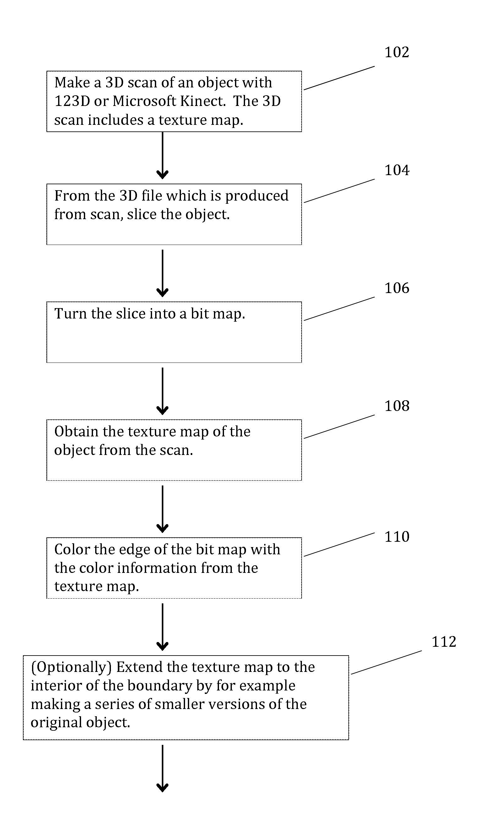
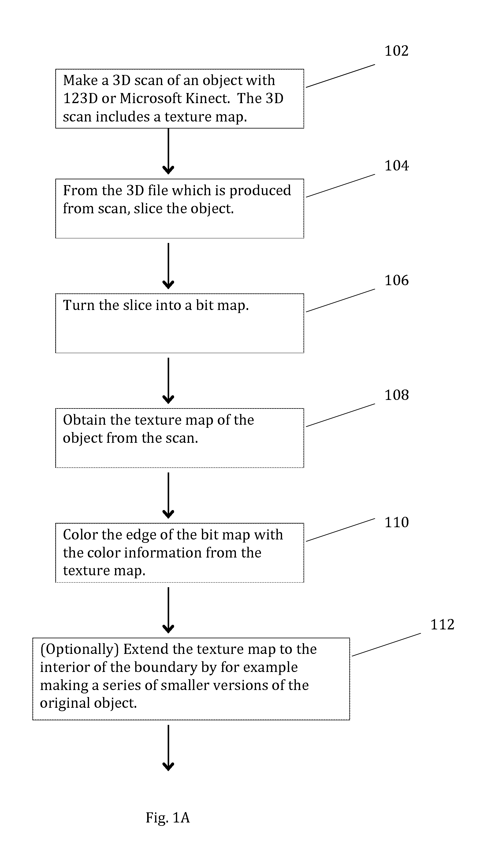
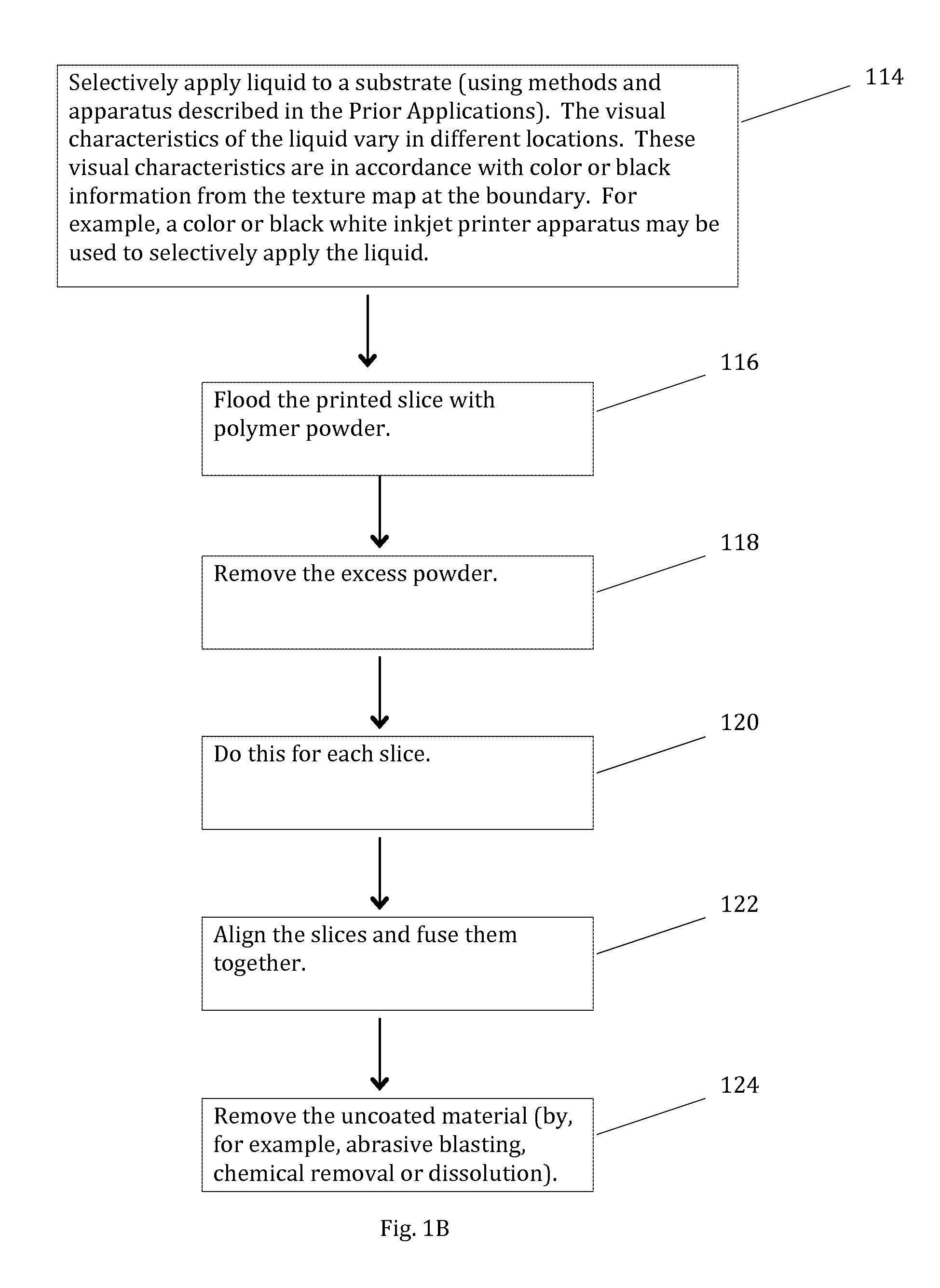
However, the prior art does not describe a process to fabricate a new 3D object from a target object in which a 3D object is sliced to form a bit map from which a texture map is obtained in order to color the edge of the bit map with color information from the texture map; and further, such that the slices are aligned and fused together and wherein uncoated material is removed by, for example, abrasive blasting, chemical removal or dissolution.

Method used


Image

  • Methods for photosculpture
  • Methods for photosculpture
  • Methods for photosculpture

Examples


example 1

Of Selective Deposit of Powder

[0058]First, powder may be selectively deposited on a substrate layer by making the powder adhere to a liquid, as follows: A liquid is selectively deposited on a substrate layer, so that some parts of the substrate layer are covered with liquid, and some are not. Then the side of the substrate layer on which the fluid was deposited is flooded with powder (e.g., the powder is poured on this side of the substrate layer). The powder adheres to the liquid. The excess powder (i.e., the powder that is not adhering to the liquid) is removed. For example, this excess powder may be removed by vacuuming. Or, for example, the substrate may simply be flipped over, so that the excess powder falls off. Or the substrate may be turned upside down and flicked with a finger. The substrate may be vibrated while the excess powder is removed, in order to facilitate the removal. In some cases, the liquid that is selectively deposited is water (or an aqueous solution that inc...


PUM

PropertyMeasurementUnit
coloraaaaaaaaaa
material propertyaaaaaaaaaa
colorsaaaaaaaaaa

Abstract

A 3D object (the “New Object”) is fabricated layer by layer by 3D printing. The shape and relative dimensions of the various parts of the New Object match that of another 3D object (the “Target Object”). In addition, the exterior of the New Object appears to be a photographic likeness of the Target Object. The “photographic” likeness is created by variations in visual characteristics of materials in the layers comprising the New Object, and in particular by variations at or near the surface of the New Object. Thus, the photographic likeness is an integral part of these layers comprising the New Object. An object is scanned, from which a texture map is obtained. A CAD model is sliced into slices (bit maps files) which are then colored by a program with the boundary to match the color or gray scale to color the appropriate pixels, derived from the texture map.

Description

[0001]This application claims the benefit of U.S. Provisional Application No. 61 / 773,810, filed Mar. 6, 2013. This application (as did the provisional application of which it claims the benefit) hereby incorporates by reference in their entirety the disclosures of the following two applications (the “Prior Applications”): (1) Methods and Apparatus for 3D Fabrication, PCT patent application PCT / US12 / 52946, international filing date Aug. 29, 2012, and (2) Methods and Apparatus for 3D Printed Composite Materials, U.S. provisional patent application 61 / 769,724, filed Feb. 26, 2013.TECHNICAL FIELD OF THE INVENTION[0002]The present invention relates generally to methods and apparatus for 3D printing.BACKGROUND OF THE INVENTION[0003]3D printing is a well known process used to reproduce a three dimensional object from a target object or digital image. What is needed is a thorough technique to match the photographic likeness of a target object by generating a new object having the same color...

Claims


Application Information

Patent Timeline
Patent Type & Authority Patents(United States)
IPC IPC(8): B29C41/20B33Y50/00B32B5/02B29C67/00G06T15/08G06T17/10B33Y10/00G06T15/04B32B3/10B29C70/68
CPCB33Y10/00B29C67/0074B29C67/0077B29C67/0088B32B5/022B32B5/024B33Y50/00B29C64/141B29C64/153B29C64/165B29C64/35B29C64/393Y02P90/02B29K2105/251B33Y30/00B33Y50/02G05B19/4099G05B2219/35134
Inventor SWARTZ, ROBERTNESS, STEPHENGORE, EUGENECRIST, BUCKLEY
Owner IMPOSSIBLE OBJECTS INC
Why Eureka
Try Eureka