Electrical and physical mounting assemblies

a technology of mounting assemblies and mounting brackets, which is applied in the direction of lighting support devices, lighting and heating apparatus, light source combinations, etc., can solve the problems of difficult rotation, time-consuming, and even impossible with traditional mounting assemblies, and the configuration of traditional mounting assemblies may not be convenient and/or tool-free adjustment of relative orientation, and the separation and/or removal of electrical devices from the base structure may be difficult and/or unsightly. , the effect of reducing the number of screws

Inactive Publication Date: 2016-07-19
SAMSON SPORTS +1
View PDF7 Cites 1 Cited by
  • Summary
  • Abstract
  • Description
  • Claims
  • Application Information

AI Technical Summary

Problems solved by technology

Such rotation may be difficult, time-consuming, or even impossible with traditional mounting assemblies.
As an example, the traditional mounting assembly may not be configured for convenient and / or tool-free adjustment of the relative orientation.
The desire for easy selective removal may be due to the expense of the electrical device (and thus risk of theft thereof) and / or a desire to stow the electrical device apart from its “use” position.
Such separation and / or removal of the electrical device from the base structure may be difficult and / or unsightly with traditional mounting assemblies.
As an example, the traditional mounting assembly may not be configured for convenient and / or tool-free separation of the electrical device from the base structure, as discussed.
As another example, removal of the electrical device from the base structure may leave unsightly wires visible to passers-by, thereby detracting from the aesthetic appeal of the base structure and leaving the wires exposed and susceptible to damage.

Method used


Image

  • Electrical and physical mounting assemblies
  • Electrical and physical mounting assemblies
  • Electrical and physical mounting assemblies

Examples


Embodiment Construction

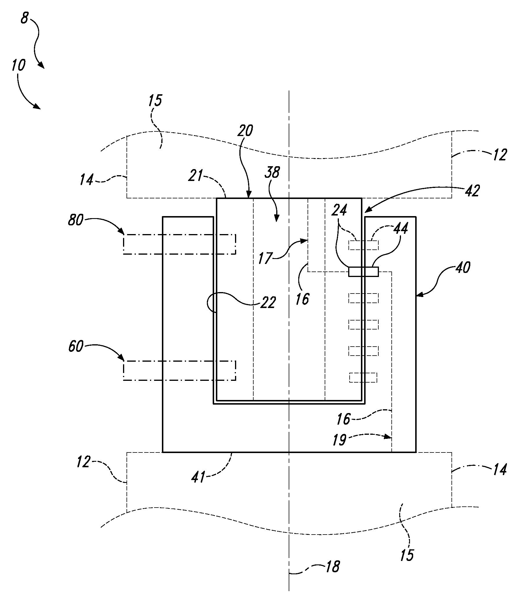
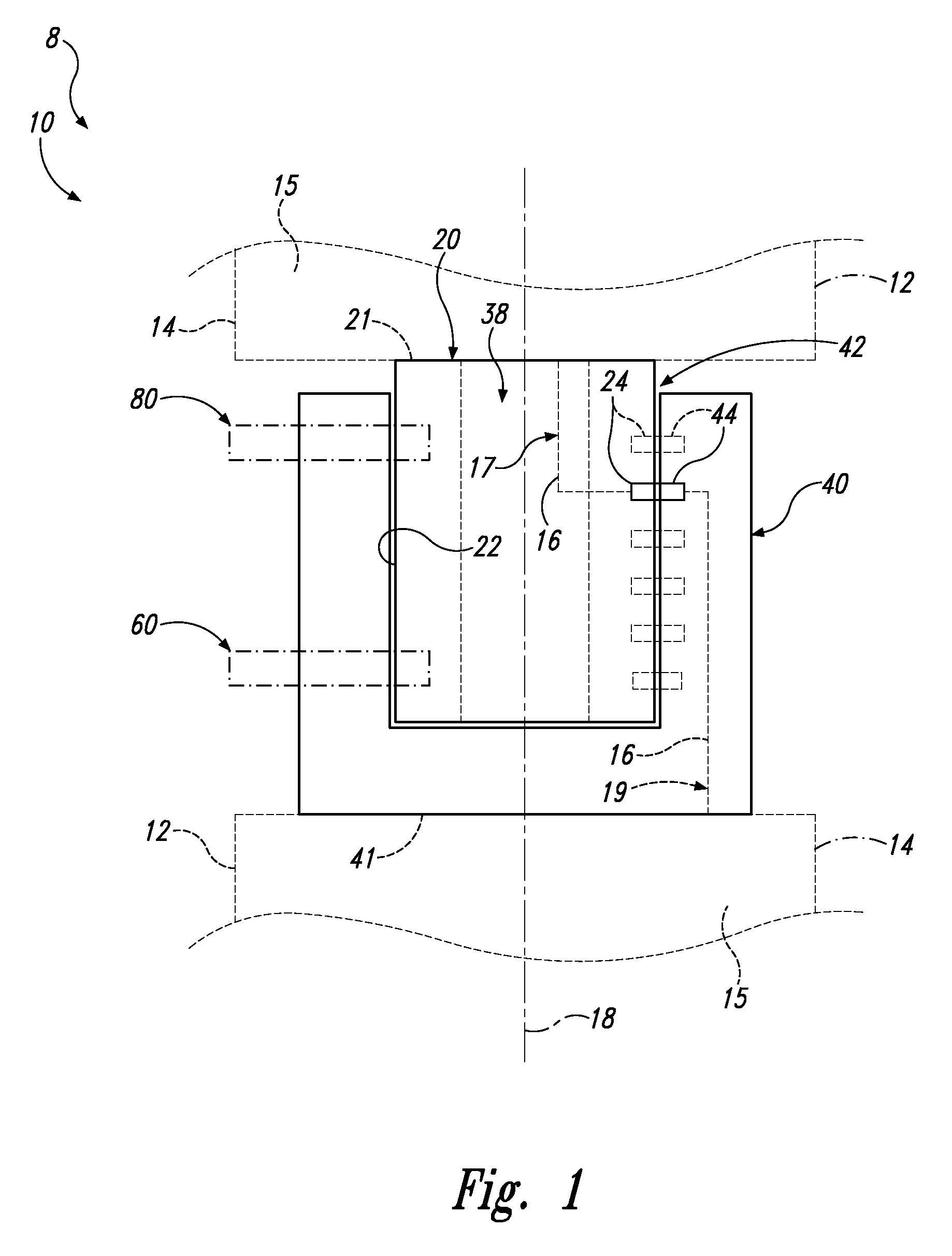
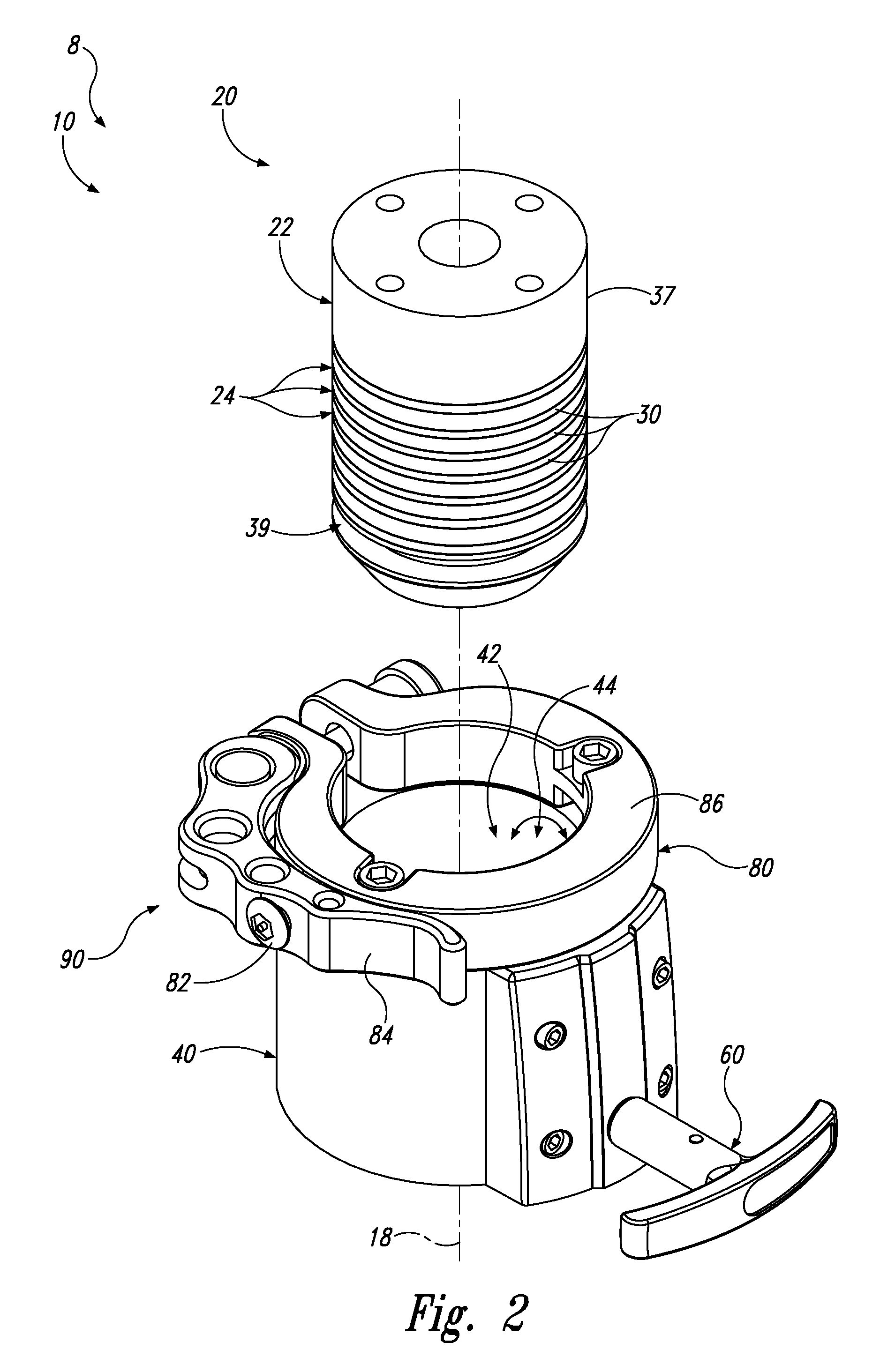
[0023]FIGS. 1-10 provide examples of electrical and physical mounting assemblies 10 according to the present disclosure, of components of electrical and physical mounting assemblies 10, and / or of electrical assemblies 8 that include and / or utilize electrical and physical mounting assemblies 10. Elements that serve a similar, or at least substantially similar, purpose are labeled with like numbers in each of FIGS. 1-10, and these elements may not be discussed in detail herein with reference to each of FIGS. 1-10. Similarly, all elements may not be labeled in each of FIGS. 1-10, but reference numerals associated therewith may be utilized herein for consistency. Elements, components, and / or features that are discussed herein with reference to one or more of FIGS. 1-10 may be included in and / or utilized with any of FIGS. 1-10 without departing from the scope of the present disclosure.

[0024]In general, elements that are likely to be included in a given (i.e., a particular) embodiment are...


PUM


Abstract

Electrical and physical mounting assemblies. The mounting assemblies include a male structure, a female structure, a retention structure, and a rotation control structure. The male structure has an outer surface and includes at least a first electrical contact that defines a portion of the outer surface. The female structure defines a receptacle that is sized to receive the male structure. The receptacle and the male structure are shaped to permit relative rotation therebetween about a rotational axis when the male structure is received within the receptacle. The female structure includes a second electrical contact that defines a portion of the receptacle. The first electrical contact and the second electrical contact are shaped to maintain electrical communication therebetween during the relative rotation. The retention structure is configured to selectively retain the male structure within the receptacle. The rotation control structure is configured to selectively restrict the relative rotation.

Description

RELATED APPLICATIONS[0001]This application claims priority to U.S. Provisional Patent Application No. 61 / 939,169, which was filed on Feb. 12, 2014, and U.S. Provisional Patent Application No. 62 / 115,076, which was filed on Feb. 11, 2015, the complete disclosures of which are hereby incorporated by reference.FIELD OF THE DISCLOSURE[0002]The present disclosure is directed generally to electrical and physical mounting assemblies for electrical devices, and more particularly to electrical and physical mounting assemblies that are configured to operably mount an electrical device to a base structure, to conduct an electric current between the electrical device and the base structure, and to facilitate both rotation of the electrical device relative to the base structure and selective separation of the electrical device from the base structure.BACKGROUND OF THE DISCLOSURE[0003]An electrical device may be mounted, attached, and / or affixed to a variety of different base structures. As examp...

Claims


Application Information

Patent Timeline
Patent Type & Authority Patents(United States)
IPC IPC(8): B60Q1/00B60Q1/04H04R1/02F21V33/00H01R35/04H04R1/40F21V21/002F21Y113/00
CPCB60Q1/0088B60Q1/0017B60Q1/0483F21V33/0056H01R35/04H04R1/026F21V21/002F21Y2101/02F21Y2113/005H04R1/403F21Y2113/13F21Y2115/10
Inventor HASBROOK, WILLIAM B.KELSEY, BRIAN T.PARNELL, SCOTT D.
Owner SAMSON SPORTS
Why Eureka
Try Eureka